AXING SPU 17XX-09 Benutzerhandbuch
Seite 4
Field of application:
The devices are only suitable for in-house distribution of RF signals. If a
device is used for other purposes, no warranty is given!
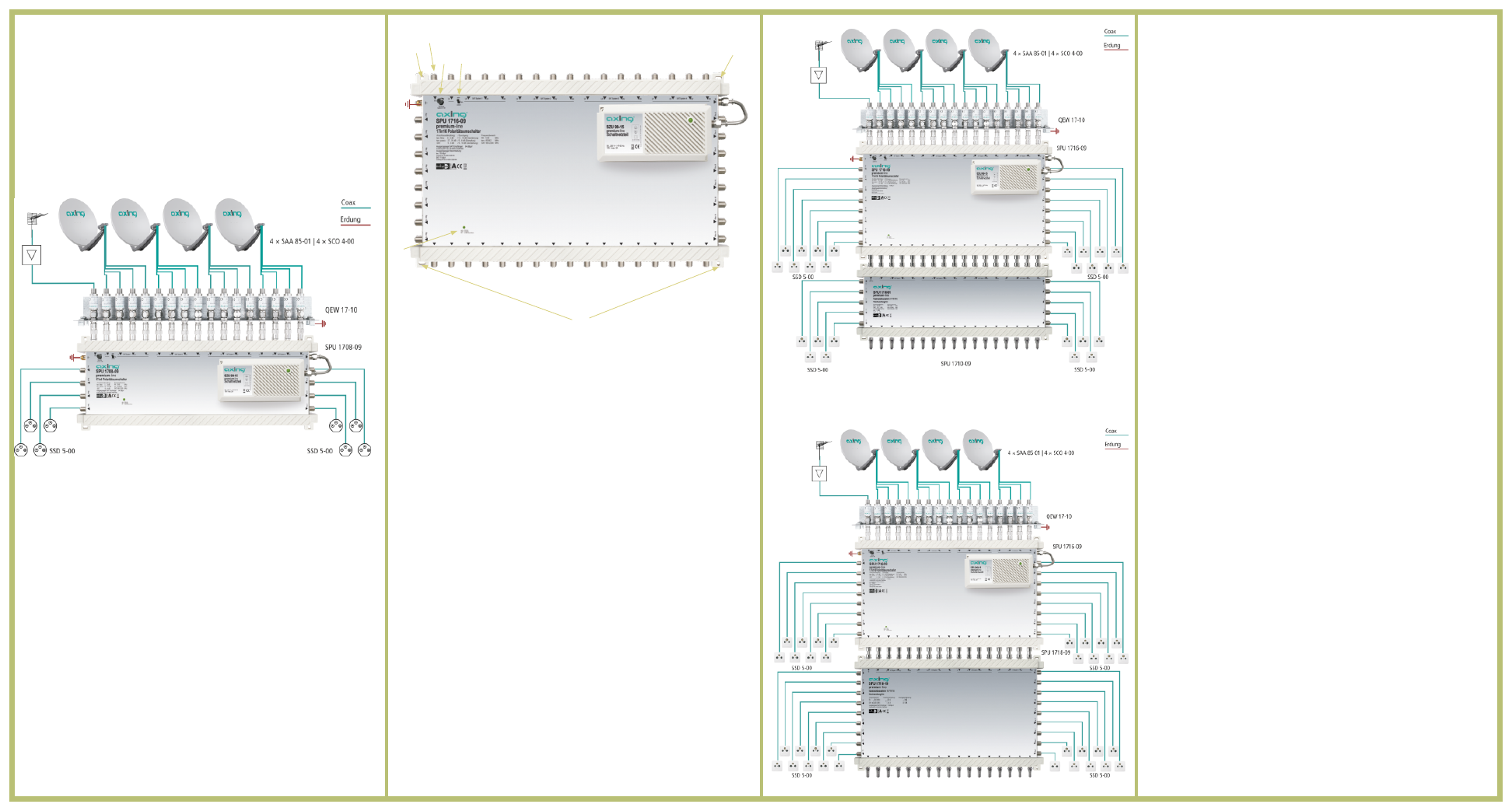
The picture shows an application example for distribution of 16 SAT IF
polarization levels including terrestrial signals (e.g. FM radio).
Grounding, Mounting and Power supply:
4
To avoid dangerous power surges (e.g. risk of fire and danger of life)
all devices must be grounded according to EN 60728-11. Use the
screw terminal at the device (1). We would therefore recommend to
use QEW Earthing angles.
4
Use the included mounting screws and the mounting holes of the
device 2().
RF-Installation:
4
Connect the SAT inputs of the multiswitch to the LNBs of your SAT
reception antenna. Connect the output signals of a terrestrial amplifier or
a CATV amplifier to the terrestrial input.
4
Connect the outputs on the left and right sides of the multiswitch to the
antenna sockets. Use highly shielded coaxial cables with F connectors.
Suitable cables and connectors can be found in the current AXING
catalogue or under www.axing.com.
4
If you don´t use cascade units to expand the multiswitch, terminate the
outputs on the lower side with the resistors CFA 11-00* enclosed.
4
If you use cascade units to expand the multiswitch, connect them with
F/F Quickfix adapters CFA 4-01.
* SPU 1716-09 incl. 17 termination resistors
Multifunction LED:
The multiswitch comes with a multifunction LED (6), which shows different
operation modes with different colours.
a
green = in operation
a
yellow = stand by (no receiver connected respc. on)
a
red = LNB short-circuit (check the cabling and rectify the error)
Level Adjustment (SPU 1716-09 and SPU 1708-09 only):
The terrestrial input of our multiswitch can be adjusted (4).
Return path
To use the return path, terrestrial path must be switched passiv (5).
Cascading (SPU 1716-09 only):
The multiswitch SPU 1716-09 can be extended with the cascade units
SPU 1710-09 and SPU 1718-19.
4
Connect the outputs of the multiswitches with the inputs of the
cascade units. Use F/F Quickfix adapters CFA 4-01 (not included in
delivery).
4
Terminate the outputs of the last cascade units with the resistors
CFA 11-00.
Remove of the power supply
When there is no mains close to the multiswitch, the power supply can
be removed and connected with an appropriate coaxial cable (max.
length 10 m).
4
Remove the F bridge (3) between the power supply and the
multiswitch.
4
Remove the power supply by pressing down the little nose of the
base plate and push the power supply to the right side; then you
can take it off.
4
Fix the power supply close to a power socket. Use the included
screws and fix the power supply at the foreseen mounting holes
(top left and bottom right )
4
Connect the DC-output of the power supply (F-female connector )
with the
DC-input of the multiswitch. Use an appropriate coaxial cable with
F-connectors.
4
Connect the power supply only to mains when all installation
works are finished
1
2
3
4
5
6
2
2
Subscriber ports
Subscriber ports
Outputs to cascade units
terr. input
16 SAT inputs