Remko mcc 1, Installation – REMKO MCC 1 Benutzerhandbuch
Seite 6
6
REMKO MCC 1
KABELFERNBEDIENUNG
Montageanweisung für
das Fachpersonal
■
Kontrollieren Sie den Verpackungs-
inhalt auf Vollständigkeit und das
Gerät auf sichtbare Transportschä-
den. Melden Sie eventuelle Mängel
umgehend Ihrem Vertragspartner.
Die Installation darf nur durch
autorisiertes Fachpersonal
vorgenommen werden.
HINWEIS
Sämtliche elektrische Installationen
sind von Fachunternehmen auszu-
führen. Die Montage der Elektro-
anschlüsse hat spannungsfrei zu
erfolgen.
ACHTUNG
Sämtliche elektrische Steck- und
Klemmverbindungen sind auf
ihren festen Sitz und dauerhaften
Kontakt zu kontrollieren und ggf.
nachzuziehen.
ACHTUNG
1. Schalten Sie die Spannungsversor-
gung frei.
2. Schließen Sie die 3-adrige
Netzzuleitung an den Klemmen L/N
der Rückseite an.
3. Klemmen Sie die 3-adrige
Steuerleitung auf den Klemmen
X/Y/E auf der Rückseite an und
montieren Sie den Festwiderstand.
4. Montieren Sie die Raumtemperatur-
regelung in einer Höhe von ca.
1,5m an der Wand.
5. Wählen Sie einen Montageort, der
eine gute Luftzirkulaton und keinen
Einfuss von Wärme-/Kältequellen
gewährleisten kann.
6. Verbinden Sie die Anschlüsse gemäß
dem elektrischen Schaltschema.
Die elektrischen Anschlüsse sind als
Festanschlüsse nach den geltenden
Bestimmungen auszuführen!
7. Kontrollieren Sie die Klemmstellen
auf Festigkeit.
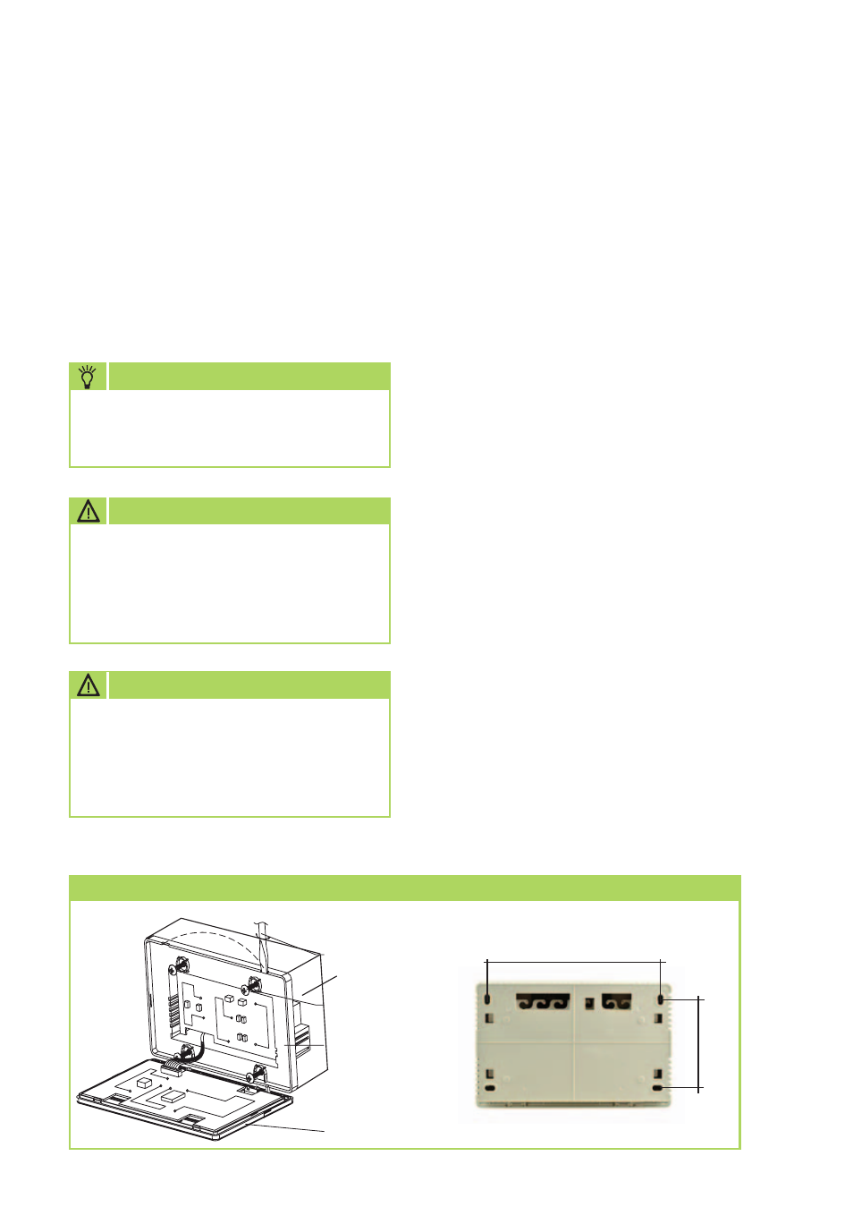
Installation
Montage des MCC 1
6,Connecting diagram of network-based air conditioning system (There are two types of indoor units, namely indoor unit
with external network interface module on the main control board or built-in network interface module in the main control board.)
5,The installation method of the central controller using electrician switch case
The thickness of the central controller cable shall be adjusted according to the length of
the cable. A proper cable tube shall be used to install the cable of the central controller.
Insert the flat tip screwdriver into the recess on the top panel of the case and slightly turn
to open the top cover of the central controller.
Dimension: as shown in the right diagram
Installation screw hole (four)
Slightly turn flat tip screwdriver to open the top cover (two)
Screws (GB845/ST3.9*25) used for fixing the central controller
Top cover
base
Power connector of the central controller 220V/AC
Communication interface to the indoor unit
OFF
COM
ON
COM
Emergency Stop Switch, used to shut down all air conditioners.
Emergency Open Switch, used to start up all air conditioners.
Installation Method
Y E
L N
ON
OFF
COM
Installation
Installation
Schraubendreher
Aufputzgehäuse
Grundplatte
Display
155
80