Connections md-52 hints – Westermo MD-52 Benutzerhandbuch
Seite 5
5
6601-2002
Connections MD-52
Hints
If any problems occur on set up of the MD-52, the LED’s will be helpful.
– PWR: The unit has power
– RD:
Data received on line B (DTE) and data transmitted on line A (DCE)
– TD
Data transmitted on line B (DTE) and data received on A (DCE)
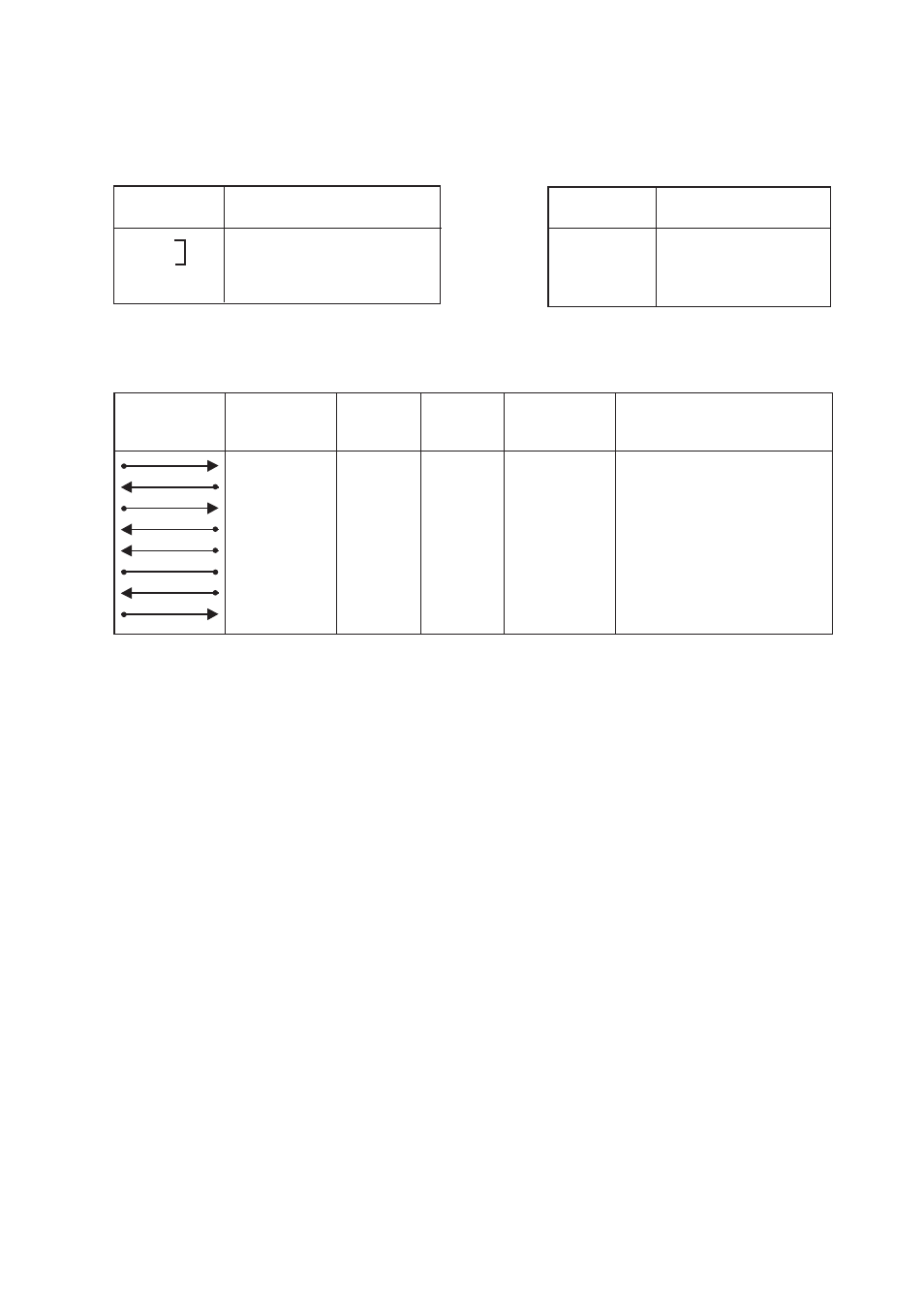
Teminal connection (RS-232-C/V.24, 9-pin D-sub/screw connections)
Direction
DTE
DCE
Connection
9-pin D-sub
3
2
7
8
6
5
1
4
8
7
6
5
2
1
4
3
1
2
3
4
–
5
–
–
103
104
105
106
107
102
109
108/2
TD/Transmitted Data
RD/Received Data
RTS/ Request To Send
CTS/ Clear To Send
DSR/ Data Set Ready
SG/Signal Ground
DCD/Data Carrier Detect
DTR/Data Terminal Ready
9-pin
screw
connection
5-pin
screw
connection
CCITT V.24
Circuit no.
Description
L
N
115/230V AC 48-62 Hz
PE
Protective
Earth
Description
Power supply AC
Connection
Power supply DC
Connection Power
supply
–
–
Voltage
+
+
Voltage