Block diagram – Laney RB6 Benutzerhandbuch
Seite 13
13
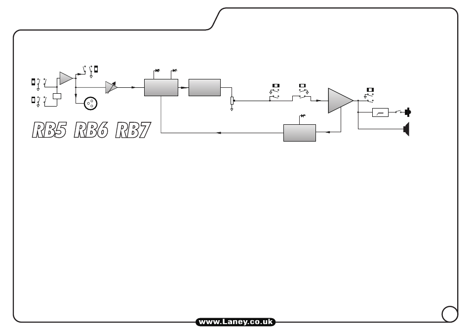
BLOCK DIAGRAM
INTERNAL
LOUDSPEAKER
OUTPUT
H.F HORN
X-OVER
D.I. OUT
TUNER OUT
GAIN
INPUT
VOLUME
FX LOOP
SEND
RETURN
ON
ACTIVE
LIMITER
SECTION
EQ SECTION
COMPRESSOR
SECTION
ACTIVE
POWER
AMP
This loop is a series type so all
your signal will go through your FX unit.
NORMAL
HIGH
PAD
Amplifier connection: In order to avoid damage, it is advisable to establish and follow a pattern for turning on and off your
equipment. With all system parts connected, turn on source equipment, tape decks, cd players, mixers, effects processors etc. BEFORE
turning on your Bass Amplifier. Many products have large transient surges at turn on and off which can cause damage to your
speakers. By turning on your Bass Amplifier LAST and making sure its Volume control is set to minimum any transients from other
equipment will not reach your loudspeakers. Wait until all system parts have stabilised; usually a couple of seconds. Similarly when
turning off your system always turn down the Volume control on your Bass Amplifier and then turn off its power before turning off
other equipment.
Cables: Never use shielded or microphone cable for any speaker connections as this will not be substantial enough to handle the
amplifier load and could cause damage to your amplifier system.
Servicing: The user should not attempt to service these products. Refer all servicing to qualified service personnel.