Leica Biosystems DM1000 TV adapters Benutzerhandbuch
Seite 2
General information
TV adapters enable video cameras to be connected to Leica
DM R/DM L and DM IR/DM IL microscopes. Besides establish-
ing a rigid mechanical connection between the microscope and
the camera, the purpose of the adapter is to adapt the micro-
scope image (field of view of the intermediate image plane) to
the chip of the CCD camera in use. However, commonly used
CCD cameras have extremely different chip sizes, resulting in
different photo and picture formats:
Selection of adapters
To guarantee useful TV microprojection in all cases, there is
therefore a choice of several TV adapters with different fixed or
variable magnification factors. Adapters with 2-stage imaging
(parallel light paths) should be used for 3 chip cameras to avoid
colour inhomogeneities or ghost images.
From this selection of TV adapters you need to select the
adapter according to the situation and your application.
Users usually want to transfer a large proportion of the field of
view to the TV screen. This proportion is usually determined by
the type of camera used and the magnification factor of the TV
adapter, according to the following formula (see Fig. 2):
Field of view imaged on the screen =
picture diagonal of camera
magnification factor of TV adapter
Example for the combination of a
2
/
3
inch camera with a picture
diagonal of 11 mm and TV adapter 0.63x
Field of view on screen =
11
= 17.5 mm
0.63
To calculate the magnification on the screen, the following fac-
tors have to be multiplied:
Magnification = objective magnification x tube factor x
TV adapter factor x
screen diagonal
camera picture diagonal
You may also need to incorporate a factor of the magnification
changer or zoom system into the calculation for the magnifica-
tion on the screen.
Types of adapter
As video cameras have different mechanical adapter mounts,
there are different adapters for C-mount, B-mount or F-mount
adaption.
C-mount adapters are the most common. Here the camera is
adapted via the C-mount thread.
B-mount and F-mount adapters need a special bayonet fitting.
Assembly of C-mount adapters
First, screw the video camera onto the C-mount adapter. Then,
depending on the microscope configuration, both parts are
mounted together onto
• the vertical photo port of the HC FSA tube
• one of the two exits of the photo port HC 100/100
• to the TV port of the DM RD
• to the side TV port of the DM IR
and fixed with the clamp screw at the side.
Assembly of B- and F-mount adapters
First, put the camera on the B- or F-mount adapter onto the bay-
onet fitting and then fix to the microscope as described above
for the C-mount adapter.
Assembly of adapters for 2-stage imaging
With these systems, the basic adapter 0.5x first has to be
screwed together with one of the chosen secondary adapters.
The further procedure is the same as for the simple adapters.
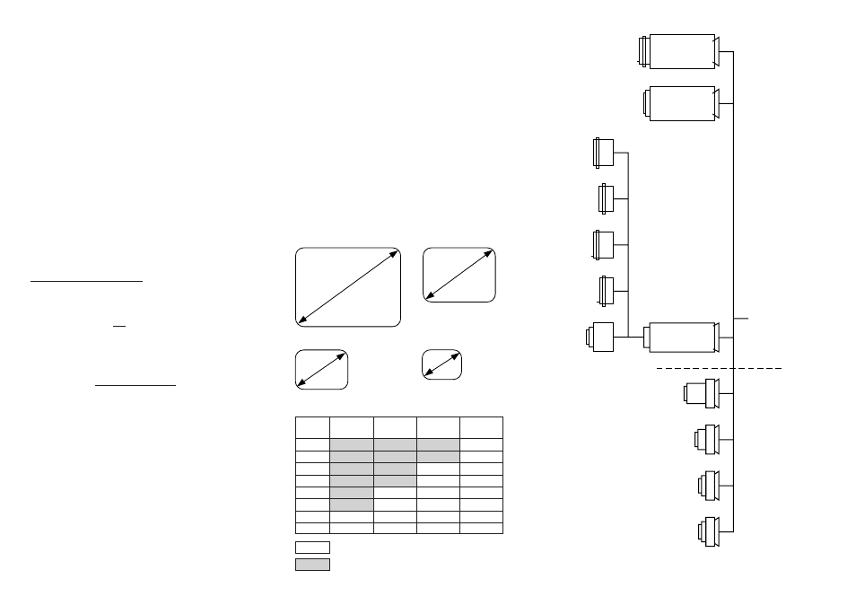
Fig. 1: Video cameras and picture formats
Leica Microsystems Wetzlar GmbH
Ernst-Leitz-Straße
D-35578 Wetzlar (Germany)
Tel. +49 (0) 64 41-29 0
Fax +49 (0) 64 41-29 25 99
www.leica-microsystems.com
Copyright ©
Leica Microsystems W
etzlar GmbH
⅐Ernst-Leitz-Stra
ß
e
⅐35578 W
etzlar
⅐Germany
200
1
⅐T
el. (0
64
41) 29-0
⅐Fax (0
64
41) 29-25
99 LEICA and the Leica Logo are registered trademarks of Leica T
e
chnology BV
.
Bestell-Nummern der Ausgaben in:
Deutsch
/Englisch 9
3
3
81
1
⅐Sach-Nr
. 540-065 Gedruckt auf chlorfrei gebleichtem Papier
. I
/0
1/FX
/FD.H.
Image size 1
″
Image size
2
/
3
″
Image size
1
/
2
″
Image size
1
/
3
″
12.8 mm
6.4 mm
8.8 mm
4.8 mm
4.8 mm
6.6 mm
9.6 mm
3.6 mm
16
mm
8 mm
11
mm
5.5 mm
Fig. 2: Monitor field of view depending on TV adapter and image size
0.35x
0.5x
0.63x
1x
C-mount
1″
C-mount
1
/
3
″
C-mount
1
/
2
″
C-mount
2
/
3
″
541 540
F-mount
1
/
2
″
541 541
F-mount
2
/
3
″
543 706
C-mount
1
/
2
″
543 702
B-mount
1
/
2
″
Sony
541 539
B-mount
2
/
3
″
Sony
541 512
541 511
541 537
Best.-Nr.
Order no.
541 510
Vario
0.33
…
1.6x
541 517
Vario
0.5
…
2.4x
541 518
541 538
0.5x
1x
1x
1x
C-mount
1
/
3
″;
1
/
2
″
B-mount
Sony
1
/
2
″
1.25x
1.25x
for single Chip Cameras
for 3 Chip Cameras
recommended combination
theoretical combination (not allowed)
Factor
Image size
Image size
Image size
Image size
TV adapter
1
″
2
/
3
″
1
/
2
″
1
/
3
″
0.35x
45.7
31.4
22.9
17.1
0.4 x
40
27.5
20
15
0.5 x
32
22
16
12
0.55x
29.1
20
14.5
10.9
0.63x
25.4
17.5
12.7
9.5
0.8 x
20
13.75
10
7.5
1
x
16
11
8
6
1.1 x
14.5
10
7.3
5.5