Scope of supply, Technical data – Fronius C-Junction Box Fronius IG 15/30 Benutzerhandbuch
Seite 4
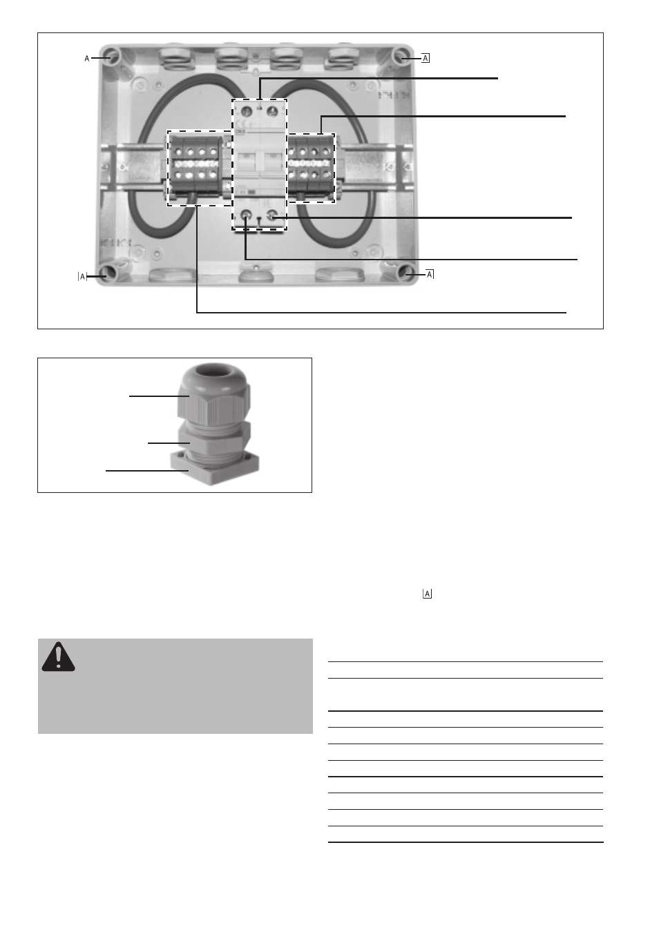
Fig.2
Inside view of DC junction box IG 15/30
Fig.3
Metric screwed conduit with strain-relief device and
fixing screw
Cabling from inverter to DC junction box
- Connect the DC+ main lead to the DC isolator and fasten with
the strain-relief device
- Connect the DC- main lead to the DC isolator and fasten with the
strain-relief device
Cabling from module strings to DC junction box
- Proceed in the same way for the DC- string cables
- Close the solar module circuits
When the installation is put into service, the inverter is connected
to the solar modules by closing the DC isolator. After this, the cover
of the DC junction box must be fitted on, and fixed in place with the
4 cover screw-fastenings.
To ensure the weathertightness of the DC junction box, also check
the transparent hinged cover on solid and tight fit.
SCOPE OF SUPPLY
- DC junction box IG 15/30
- 2 x M25 metric screwed conduits
- 8 x M16 metric screwed conduits
- 1 breather plug for ventilation
- 4 cover screw-fastenings with handles
- 4 screws, 4 dowels for wall-mounting of DC junction box
TECHNICAL DATA
Max. input voltage in open circuit
530 V
Max. input current* at
400V DC
7 A
150V DC
20 A
Max. number of strings
4
Terminals for maximum diameter of a line cross section
6 mm ²
Metric screwed conduits for fastening cables DC IN
M16
Metric screwed conduits for fastening cables DC OUT
M25
Degree of protection
IP54
Safety class
II
Ambient conditions
-25°C to +55°C
Dimensions(mm)
220x168x112,5
* (The input current must be determined by linear interpolation)
Strain relief device
Metric screwed conduit
Fixing screw
DC(-) string connections
Tightening torque = 0.8 Nm
Terminals for DC(-) main lead
Tightening torque = 2.0 Nm
Terminals for DC(+) main lead
Tightening torque = 2.0 Nm
DC(+) string connections
Tightening torque = 0.8 Nm
DC isolator
WARNING! Danger of solar module voltage. The solar
modules must be electrically dead when you connect
them to the DC junction box! First connect the string
cables to the terminals, and only then close the circuit
in the string (e.g. if you have a multicontact terminal
unit, leave it open until the last minute and only close
it after all the other installation work is finished).
- With all circuits open, connect all DC+ string cables to the red
terminal strips
- Tighten the strain-relief devices on the DC+ side
NOTE! When connecting up more than two strings, first connect
the two strings nearest to the wall and fix them with the M16 metric
screwed conduit. Only after you have done this, lead in and screw
down the two outside cables, so as to ensure “Degree of protection
IP54”.