Multi-Contact MA102 Benutzerhandbuch
Seite 3
Advanced Contact Technology
www.multi-contact.com
3 / 4
1
2
A
B
D
C
ØG
ØE
ØF
Tab. 1
HSS
3
Tab. 2
M B
4
Montagebolzen
Assembly tool
Bestell-Nr.
Order No.
für Buchsen
for sockets
Abmessungen in mm
Dimensions (mm)
A
B
C
D
E
F
G
MB0,76
25.0029
EB0,76
55
50
5
0,9
5
2,4
0,76
MB1
25.0030
EB1
56,9
50
6,9
0,9
5
2,4
1
MB2
25.0031
EB2, EB2-A, EB2-F, EB2-WR
63,5
50
13,5
1,6
7
3
1,9
Buchsen
Sockets
Bohrung
Drill hole
Metallplatten (mm)
Metal panels (mm)
Kunststoffplatten (mm)
Plastic panels (mm)
Max. Buchsen-Ø (mm)
Max socket Ø (mm)
EB0,76, EB1
Ø 2,7
1 - 3
1 - 3
4
EB2, EB2-A, EB2-F, EB2-WR
Ø 4,9
1 - 6
3 - 6
7
+0.05
0
+0.1
0
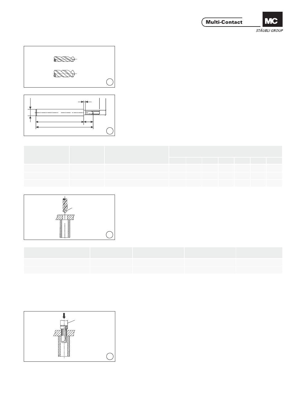
Erforderliches Werkzeug
Tools required
(ill.1)
HSS Bohrer Ø 2,7mm
HSS Bohrer Ø 4,9mm
(ill.1)
Drill HSS Ø 2,7mm
Drill HSS Ø 4,9mm
(ill. 2)
Abmessungen siehe Tab. 1
(ill. 2)
Sizes, see Tab. 1
Montage
Assembly
(ill. 3)
Fronttafel bohren und einseitig ansen-
ken (ca. 0,5x45°).
(ill. 3)
Drill hole and then countersink the
front panel on one side (approx.
0,5x45°).
Als Aufl age der Fronttafel wird vor-
zugsweise ein Kunststoffrohr verwen-
det. Der Durchmesser des Aufl ageroh-
res richtet sich nach den gewählten
Lochabständen.
As an assembly support for the front
panel, a plastic tube can be used. The
tube diameter depends upon the de-
sired distances between the sockets.
(ill. 4)
Isolierteil mit passendem Montagebol-
zen MB (siehe ill. 2) einpressen.
(ill. 4)
Press in insulation with the assembly
tool MB (see ill. 2).