Varyscan micro 150hti – JB-Lighting Varyscan Micro 150 HTI Benutzerhandbuch
Seite 17
Varyscan MICRO 150HTI
17
JB-lighting Lichtanlagentechnik GmbH Sallersteigweg 15 D-89134 Blaustein 07304-9617-0
channel no.
channel no.
channel no.
channel no.
5 shutter closed
dimmer 0-100%
shutter open
shutter closed
strobe effect in different speeds
shutter open
6 Stop of pan and tilt movement abruptly
Stop of pan and tilt movement smoothly
7 Pan movement fine
8 Tilt movement fine
DMX 000
DMX 001-135
DMX 136-137
DMX 138-139
DMX 140-243
DMX 244-255
DMX 000-127
DMX 128-255
DMX 000-255
DMX 000-255
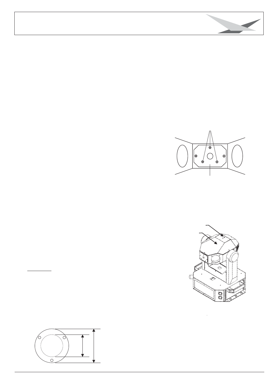
3.5 Optimizing lamp alignment
fan
2
Sketch: backside view of the head
lamp holder
Switch on the Varyscan and project gobo no. 1 (beam)
on a white wall in a 90° angle. The distance between
Varyscan and wall should be 6 to 12 meters.
Turn the three screws (no. 2, displayed in the drawing)
to the right until the end position is reached. Afterwards
turn all three screws one rotation to the left. This is the
standard setting at factory.
Center the spot by turning the three screws.
Adjust the lamp by turning one screw at a time to the left
until the Varyscan reached the maximum of light output
and even illumiantion.
3.6 Focusing
Use a screwdriver to adjust the focus to the desired
projection distance. (See drawing).
3.7 Changing gobos
Warning: Disconnect fixture from mains, and allow
hot lamp to cool down for at least 30 minutes!
Unscrew the five screws holding the top cover of the head and
remove the head. (See drawing).
The gobos can be removed by loosening the three screws M2.
For the design of custom made gobos please have a look at
the enclosed technical drawing:
Diameter:
26mm
Diameter image:
17mm
Mounting holes:
diameter 2,1mm
reference diameter 23mm
allocation 3x120°
Adjust screw
Top cover
17
mm
26
mm