Connections – Westermo MM-14 Benutzerhandbuch
Seite 11
11
6186-2003
Direction
Pin
Description
no.
Receiver
1
(R+)
Receiver
2
(R–)
Transmitter
3
(T+)
Transmitter
4
(T–)
5
Shield
Connections
Line connection
(5-position screw-terminal)
Direction
Connection no.
ITU-T V.24
Description
9-pos
25-pos
8-pos
Description
I
3
2
6
103
TD/Transmitted data
O
2
3
5
104
RD/Received Data
I
7
4
8
105
RTS/Request To Send
O
8
5
7
106
CTS/Clear To Send
O
6
6
1
107
DSR/Data Set Ready
–
5
7
4
102
SG/Signal Ground
O
1
8
2
109
DCD/Data Carrier Detect
–
–
9
–
–
PWR +12V
–
–
10
–
–
PWR –12V
I
4
20
3
108/2
DTR/Data Terminal Ready
I = Input, O = Output on MM-14
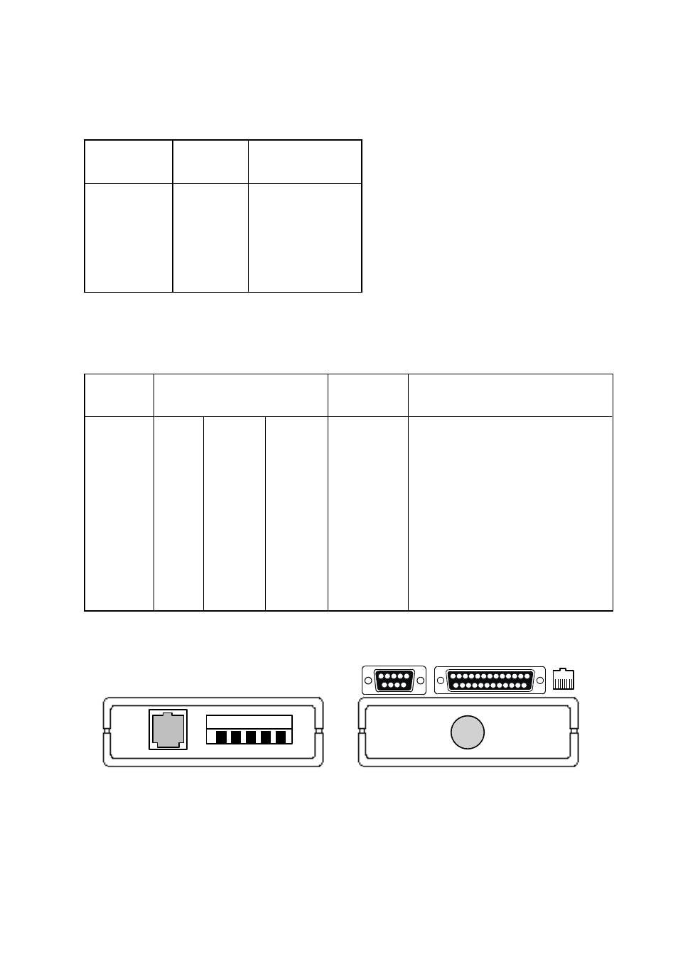
Terminal connection (DCE)
(RS-232-C/V.24, 25/9-pos D-sub, male/female or RJ 45)
LINE
1 2 3 4 5
Supply
connection
to PS-8
Line connection
5-position
screw-terminal
RS-232-C/V.24
9-/25-position D-sub
male or female connector
8-position modular jack RJ-45
Cable approx.
20 cm to
connector