Multi-Contact MA220 Benutzerhandbuch
Seite 4
Advanced Contact Technology
4 / 8 www.multi-contact.com
9
10
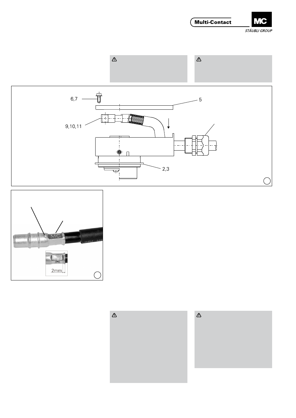
Crimpen
Crimping
Achtung
Gehäuseunterteil (1) und im
Bedarfsfall Kabelverschraubung,
vor Vercrimpen auf Leitung
auffädeln!
Attention
Before crimping, pass the cable
through the lower part of the
housing (1) and the cable gland if
appropriate�
(ill. 9)
Crimpzange mit Crimpeinsatz TB11
(25 mm²) bzw. TB13 (35 mm²) be-
stücken� Einzelleiter in die Crimphül-
se des Kontaktstückes (9, 10, 11)
einführen bis sie im Sichtloch (ill� 10)
der Crimphülse erscheinen� Leiter in
Crimphülse vercrimpen� Crimpzone
beachten! Leiter muss vor und nach
Vercrimpen im Sichtloch sichtbar sein!
Leiter darf sich nicht aus der Crim-
phülse herausziehen lassen!
(ill. 9)
Fit crimping insert TB11 (25 mm²)
or TB13 (35 mm²) into the crimping
pliers� Insert the individual conductors
into the crimping sleeve of the contact
piece (9, 10, 11) until they appear in
the control hole (ill� 10) of the crimp-
ing sleeve� Crimp conductor in crimp-
ing sleeve� Observe crimping zone!
After / before crimping, the conductor
must be visible in the control hole�
It must not be possible to pull the con-
ductor out of the crimping sleeve�
Einbauen der Kontaktstücke
Fitting the contact pieces
Leiter durch Öffnungen der Kabelver-
schraubungen zurückziehen, danach
Kontakt (9, 10, 11) wieder lagerichtig
auf Kontaktstifte von Stift-(2) bzw�
Buchsengehäuse-Vorderteil (3) ste-
cken�
Pull back the conductors through the
openings of the cable glands� Place
the contact (9, 10, 11) in the correct
position on the contact pins of pin (2)
or socket (3) housing front part�
Achtung
Kabelverschraubung erst nach
lagerichtigem Aufstecken der
Kontaktstücke und Ausrichten
der Leiter im Gehäuse-Unterteil
(1) festschrauben!
Drehmoment Verschraubung:
3,5 Nm
Drehmoment Überwurfmutter:
2,5 Nm
Deckel (5) mittels Sechskant-
Schraubendreher SW2,5 mit
Zylinderschrauben (6, 7) wieder
aufschrauben�
Attention
Do not tighten the cable gland
until the contact pieces have
been correctly fitted on the pins
and the conductors aligned in the
housing bottom part (1)
Cable gland torque: 3.5 Nm
Grip nut torque: 2.5 Nm
Screw the cover (5) back in place
with screws (6, 7) using hex key
wrench A/F 2�5�
Kabelverschraubung
Cable gland
Crimpbereich
Crimping zone
Sichtloch
Control hole