Multi-Contact MA220 Benutzerhandbuch
Seite 7
Advanced Contact Technology
www.multi-contact.com
7 / 8
13
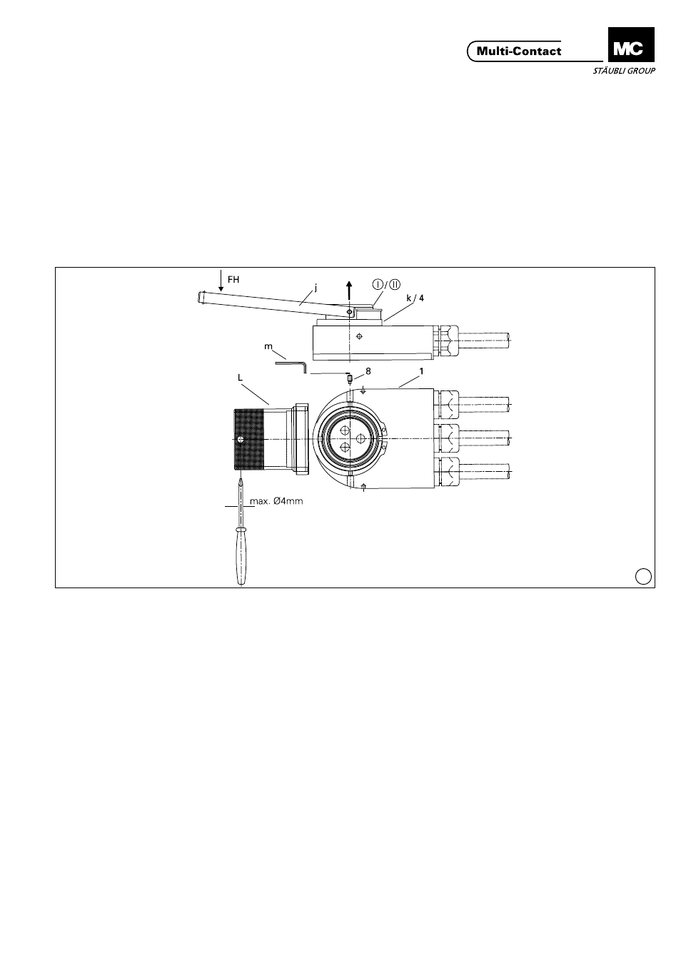
(ill. 12)
Gewindestift (8) herausschrauben mit-
tels Sechskant-Schraubendreher SW2
(m)� Den Haltering (4) herausschrau-
ben mittels Montagering (L) und dem
Schraubendreher (n) als Drehhebel�
An die Stelle des Halterings (4) den
Montagestützring (k) setzen� Dieser
hat 2 Stützflächen, I und II.
Fläche I ist für die Demontage des
Stiftgehäuse-Vorderteils, Fläche II für
die Demontage des Buchsengehäuse-
Vorderteils�
(ill. 12)
Unscrew the setscrew using a hex key
wrench A/F 2 (m)� Unscrew the secur-
ing ring (4) by means of the assembly
ring (L), turning with the screwdriver
(n) as a lever� Fit the supporting ring
(k) in the place of the securing ring
(4)� The support ring has 2 supporting
surfaces, I and II�
Surface I is for dismantling the front
part of the pin housing, and surface
II for dismantling the front part of the
socket housing�
(ill. 13)
Danach das Demontagewerkzeug
(j) am Stift-(I)bzw� Buchsengehäuse-
Vorderteil (II) in den vorgesehenen
Bohrungen ansetzen� Die Schenkel
des Montagewerkzeuges zusammen-
drücken und gleichzeitig in Richtung
FH drücken und so das Stift- (I)bzw�
Buchsengehäuse-Vorderteil (II) heraus-
hebeln�
Das neue Stift-(I)bzw� Buchsengehäu-
se-Vorderteil (II) lagerichtig (Nut pas-
send zu Führungsstift) einbauen (von
Hand eindrücken)� Es ist unbedingt
darauf zu achten, dass das Stift- bzw�
Buchsengehäuse-Vorderteil in das
richtige, entsprechende Gehäuse-Un-
terteil (1, siehe Aufschrift) eingesetzt
wird� Haltering (4) mittels Montage-
ring (L) wieder aufschrauben, danach
den Gewindestift (8) zur Fixierung
des Haltering‘s (4) mittels Sechskant-
Schraubendreher SW2 (m) wieder
einschrauben�
(ill. 13)
Then insert the extraction tool (j) into
the holes provided in the front part of
the pin (I) or socket (II) housing� Press
together the arms of the assembly
tool and at the same time press in
direction FH so as to lever out the pin
(I) or socket (II) housing front part�
Fit by hand the new pin (I) or socket
(II) housing front part in the correct
position (slot in line with guide pin)�
Check carefully that the pin or socket
housing front part is fitted into the
correct housing bottom part (1, see
marking)� Screw the securing ring (4)
back in place with the assembly ring
(L), then screw in the setscrew (8) to
fix the securing ring (4) using a hex
key wrench A/F 2 (m)�