Multi-Contact MA265 Benutzerhandbuch
Seite 5
Advanced Contact Technology
Advanced Contact Technology
8 / 16 www.multi-contact.com
www.multi-contact.com
9 / 16
9
N
10
13
B
14
12
11
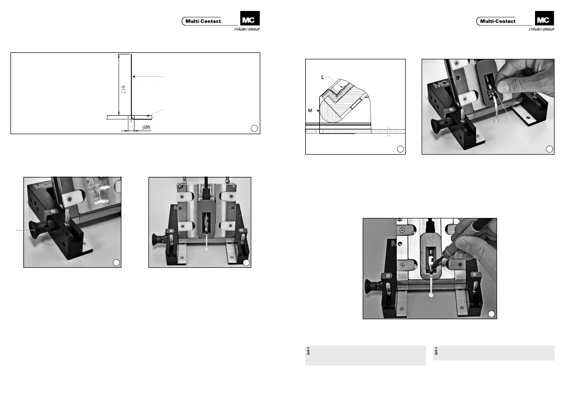
Vorbereitung der Flachbandleiter
Preparation of the flat ribbon conductors
(ill. 9)
Flachbandleiter sollen eine Länge von 61 mm haben bzw. auf
diese Länge zugeschnitten werden. Es können Flachbandlei-
ter bis zu einer Breite von 6,5 mm montiert werden.
(ill. 9)
Flat ribbon conductors should have a length of 61 mm or be
cut to this length� Ribbon conductors with a width of up to
6,5 mm can be fitted.
Einsetzen der Paneldose in das Hilfswerkzeug
PV-WZ-JB/LC
Inserting the junction box in the auxiliary tool
PV-WZ-JB/LC
(ill. 10)
Bevor die Paneldose in das Montagewerkzeug eingesetzt wird,
sollte sich der Arretierbolzen “N” in der vorgespannten Aus-
gangsposition befinden.
(ill. 10)
Before the junction box is inserted in the assembly tool, the
locking pin “N” should be in the spring-loaded starting posi-
tion�
(ill. 11)
Um die Paneldose in das Montagewerkzeug einzusetzen,
wird die Paneldosenaufnahme etwas zurückgedrückt, so
dass sich der Arretierstift nach hinten schiebt (Druckfeder
gespannt)� In dieser Position wird die Paneldose eingelegt
und das Anschlusskabel in die Federklammer des Kabelhalte-
bügels eingedrückt� Nach dem Einlegen der Paneldose wird
die Paneldosenaufnahme wieder etwas nach vorne bewegt
(Ausgansposition), so dass der Arretierstift in die dafür vorge-
sehene Öffnung in der Paneldose einfahren kann (Druckfeder
entspannt)�
(ill. 11)
To insert the junction box in the assembly tool, the junction
box receptacle is pushed back slightly so that the locking pin is
moved backwards (pressure spring under tenstion)� In this po-
sition the junction box is inserted and the connecting cable is
pressed into the spring clips of the calbe holder� After inserting
the junction box, the junction box receptacle is again moved
slightly forwards (starting position) so that the locking pin can
enter the opening provided for it in the junction box (pressure
spring de-tensioned)�
Flachbandleiter
Flat ribbon conductor
PV-Modul
PV module
Montage der Flachbandleiter
Fitting the flat ribbon conductors
(ill. 12)
Flachbandleiter “M” über die Stirnseite des Gehäuses leicht
straff gespannt (evtl� mit Hilfswerkzeug Pinzette und Schrau-
bendreher) bis zum Kontaktteil “L” mit dem aufgebrachten
Lötzinn anlegen.
(ill. 12)
Draw the ribbon conductor “M” over the front of the housing
under slight tension (if necessary with the aid of tweezers and
screwdriver) as far as the tinned contact part “L”.
(ill. 13)
Fixieren Sie den Flachbandleiter mit dem dem lose mitgelie-
ferten PV-Bügel „B“, d�h� drücken Sie den PV-Bügel in die
dafür vorgesehene Aussparung in der Paneldose bis zum
Anschlag ein�
(ill. 13)
Fix the flat ribbon conductor with the PV clip “B” (supplied
separately), i�e� press the PV clip into the slot in the junction
box as far as the limit�
(ill. 14)
Flachbandleiter mit dem PV-Kontaktteil verlöten. Löttempe-
ratur 320 °C – 450 °C (bei Verwendung des empfohlenen
Flussmittels)�
(ill. 14)
Solder ribbon conductor to the PV contact part� Solder tem-
perature 320 °C – 450 °C (with use of the recommende flux).
Hinweis:
Es ist unbedingt notwendig, zusätzlich Lötflussmittel zu-
zuführen. MC empfiehlt die Verwendung des Lötflussmittels
950E (www.kester.com).
Note:
It is crucial that you add additional soldering flux. MC
recommends using 950E soldering flux (www.kester.com).