Col 100 full act – Allied Telesis AT-8600 Series Switch Benutzerhandbuch
Seite 9
Installation & Safety Guide
9
6.
Place the switch in its operating location
If installing the switch in a rack:
•
Remove the rubber feet on the bottom of the switch with a flat-head
screwdriver.
•
Attach the two rack-mounting brackets to the switch with the screws
provided.
•
Mount the switch in the rack using standard screws (these are not
provided).
7.
Check the supply voltage and the switch’s rated voltage
AT-8600 Series switches are fitted with a universal main power supply that
will function over the range 100–240 VAC and 50–60 Hz.
The specific power supply requirements for a particular model are clearly
displayed on the rear or underside of the switch. If the supply is outside the
accepted range for the switch, the switch may not operate or damage to
the switch may result.
8.
Apply AC power to the switch
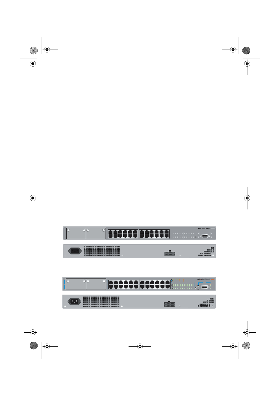
Plug the power cord into the AC power connector on the switch’s rear
panel as shown in Figure 1. The Fault LED should flash for approximately 10
seconds as the switch runs internal tests. If the LED continues to flash,
refer to the AT-8600 Series Hardware Reference for troubleshooting
information.
Figure 1: AT-8624T/2M front and rear panel with AC power inlet.
Figure 2: AT-8624PoE front and rear panel with AC power inlet
1
3
5
7
9
11
13
15
17
19
21
23
2
4
6
8
10
12
14
16
18
20
22
24
LINK
MODE
LINK
MODE
FAULT
RPS
MASTER
PWR
MODE
1
3
5
7
9
11
2
4
6
8
10
12
13
15
17
19
21
23
14
16
18
20
22
24
STATUS
RS-232
TERMINAL PORT
26
COL
100
FULL
ACT
AT-8624T/2M
Advanced Fast Ethernet Switch
25
25
1
3
5
7
9
11
13
15
17
19
21
23
2
4
6
8
10
12
14
16
18
20
22
24
FAULT
RPS
MASTER
PWR
MODE
1
3
5
7
9
11
2
4
6
8
10
12
13
15
17
19
21
23
14
16
18
20
22
24
STATUS
26
RS-232
TERMINAL PORT
COL
HALF DUP
FULL DUP
ACT
100 LINK
10 LINK
ACT
PD ON
MAX CURRENT
PD ERR
AT-8624POE
Layer 3 Fast Ethernet Switch
8600isg.fm Page 9 Wednesday, June 22, 2005 2:46 PM