M12 a-kodierung – Northern Connectors Binder M12 A-Coded Power Connectors Benutzerhandbuch
Seite 3
4
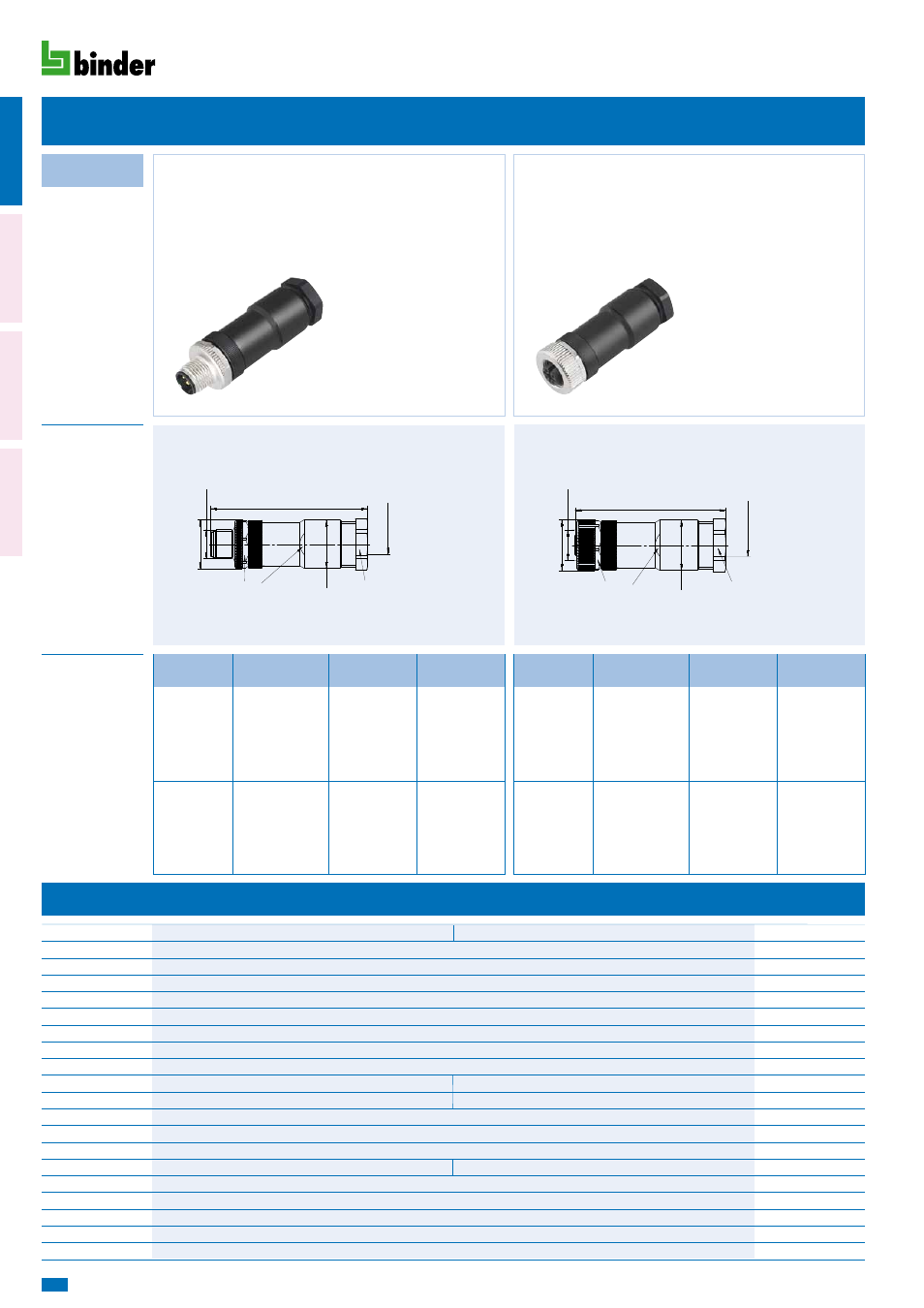
Powersteckverbinder Serie 713
Power connectors series 713
Bestell-Nr.
Ordering-No.
Bezeichnung
Description
Abbildung
Figure
Maßzeichnung
Drawing
Kabelstecker, Power
Male cable connector, Power
4
5
4
5
4 5
Technische Daten
Specifications
Polzahl
Steckverbinder Verriegelung
Anschlussart
Anschlussquerschnitt
Kabeldurchlass
Schutzart
Mechanische Lebensdauer
Obere Grenztemperatur
Untere Grenztemperatur
Bemessungsspannung
Bemessungs-Stoßspannung
Verschmutzungsgrad
Überspannungskategorie
Isolierstoffgruppe
Bemessungsstrom (40°C)
Durchgangswiderstand
Material Kontakt
Kontaktoberfläche
Material Kontaktkörper
Material Gehäuse
Number of contacts
Connector locking system
Termination
Wire gauge
Cable outlet
Degree of protection
Mechanical operation
Upper temperature
Lower temperature
Rated voltage
Rated impulse voltage
Pollution degree
Overvoltage categorie
Material group
Rated current (40 °C)
Contact resistance
Material ot contact
Contact plating
Material of contact body
Material of housing
schraub/screw
schraubklemm mit Aderendhülse/screw clamp with ferules
schrauben/screw max. 1,5 mm
2
(max. AWG 16)
8–10 mm
IP 67
> 100 Steckzyklen/> 100 mating cycles
+ 85 °C
– 40 °C
250 V
125 V
2500 V
1500 V
3
II
ll
8 A
Kontakt/contact 1–4 8 A, Kontakt/contact 5 2 A
≤ 3 mΩ (Gold/gold)
CuZn (Messing/brass)
Au (Gold/gold)
PA
PA
M1
2 x 1
Ø 20,2
~63
SW 18 mm
Ø 20
SW 19 mm
Kabel Ø 8–
10
Cable Ø 8–
10
M12 A-Kodierung
Kabeldose, Power
Female cable connector, Power
M1
2 x 1
Ø 20,2
~63
SW 18 mm
Ø 20
SW 19 mm
Kabel Ø 8–
10
Cable Ø 8–
10
M12 A-Kodierung
8–10 mm
8–10 mm
8–10 mm
8–10 mm
99 0430 19 04
99 0436 19 05
99 0429 19 04
99 0437 19 05
Polzahl
Contacts
Polzahl
Contacts
Bestell-Nr.
Ordering-No.
Bestell-Nr.
Ordering-No.
Kabeldurchlass
Cable outlet
Kabeldurchlass
Cable outlet
Anschlussquerschnitt
Cross section
Anschlussquerschnitt
Cross section
1,5 mm
2
1,5 mm
2
1,5 mm
2
1,5 mm
2
7/
8‘
‘
M12
-A
M12
-S
M1
2-T