AXING BVS 14-66 Benutzerhandbuch
Seite 4
Field of application:
The devices are suited only for amplifying radio and television signals in the
house! If the device is used for other purposes, no warranty is given!
The illustrations show application examples for the distribution in star (1) and
tree structure (2).
Grounding and Mounting:
To avoid dangerous power surges (e.g. risk of fire and electrocution), all
devices have to be grounded. Use the screw terminal at the device (3).
Use the mounting screws included in the delivery and the mounting holes of
the devices (4).
RF Installation:
For connecting the BVS 14-66 you either need two adapters PG 11/F female (CFA 12-00) or PG 11/IEC female (CKA 12-00) or PG 11 cable glands /
mountings (on request). This adapters are not part of the delivery.
Connect the input of the amplifier to the video interconnection point. Connect the output of the amplifier to the antenna sockets or the taps used.
Use a highly shielded coaxial cable. Suited cables and can be found in the current AXING catalogue or at www.axing.com.
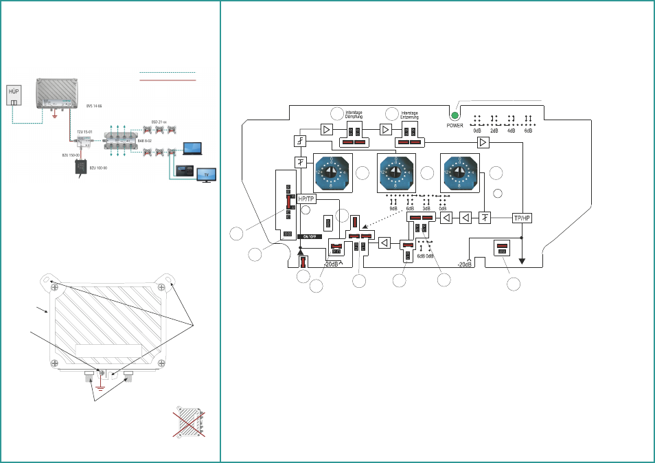
Test ports:
The outside test ports ( -20dB ) have F-female connectors, the test port at the input is bi-directional. This test port has to be activated (1a) or deactivated
(1b) with the adjacent jumper.
Downstream Adjustments:
Gain and slope can be adjusted using the PCB switches (2 and 3) in the forward frequency range. The jumpers (4 and 5) are used to adjust the interstage
attenuation and slope.
To compensate a pre-emphasis a cable simulator (BZU 80-02) can be pluged in (6)
Upstream Adjustrments:
Per default the return path is active. It can be switched passive with the jumpers (7), (8) and (9).
With the PCB switch (10) the attenuation of the return path is adjusted.
The jumpers (11 and 12) are used to adjust the interstage attenuation and slope.
With the jumper (13) the attenuation of the output is adjusted.
Power indicator LED:
green = in operation
off = no power supply
Rückkanal
aktiv
passiv
Rückkanal
aktiv
passiv
Rückkanal
aktiv
Rückkanal
passiv
Kabelnachbildung optional
Dämpfung
Interstage
Entzerrung
Interstage
Dämpfung
1a
7
1b
6
8
9
2
3
4
5
10
12
13
11
The amplifier may only be monted at a
wall as shown above.
Remote power supply:
The BVS 14-66 is supplied via the AC connection, via the input or the output.
It is prohibited to loop through the AC remote power supply voltage through the CFA 12-00 or CKA 12-00 adapters!
If a second BVS 14-66 is installed in a cascade connection, the AC remote power supply voltage can be fed through the left sided AC connection and be
transferred through a PG11 / F- connector to the second amplifier.
If several BVS 14-66 will be cascaded and remote powered, PG 11 cable glands / mountings have to be used.
The remote powering can be fed through the PG 11 cable gland / mountings or through the left sided AC connection.
Test ports
Input
Output
3
4
AC
Connection
Upstream and Downstream (Coax)
Power supply/Grounding