Varyscan 3 special 250msd, Operation, 1 dip switches – JB-Lighting Varyscan 3 Special 250 MSD Benutzerhandbuch
Seite 18
Varyscan 3 Special 250MSD
19
JB-lighting Lichtanlagentechnik GmbH Sallersteigweg 15 D-89134 Blaustein Tel. ++49-7304-9617-0
-1
-2
-4
-8
-16
-32
-64
-128
-256
-Mode
DIP
ON
1 2 3 4 5 6 7 8 9 10
The Varyscan can be opperated either in 6 channel or 8
channel mode depending on the lighting control console.
The main advantage of the 8 channel mode is that every
effect is assinged to a seperate channel. Programming
therefore is less complicated.
If your lighting control console is only able to control 6
channels per unit, you have to assign the Varyscan to
6 channel mode.
DMX-output of JB-lighting consoles:
JB-lighting DMX-Controller
6 channel
JB-lighting ScanControl
6 and 8 channel
JB-lighting LICON 1
6 and 8 channel
-1
-2
-4
-8
-16
-32
-64
-128
-256
-Mode
DIP
ON
1 2 3 4 5 6 7 8 9 10
-1
-2
-4
-8
-16
-32
-64
-128
-256
-Mode
6 channel
8 channel
DIP switch 10
OFF
DIP switch 10
ON
-1
-2
-4
-8
-16
-32
-64
-128
-256
-Mode
DIP
ON
1 2 3 4 5 6 7 8 9 10
DIP
ON
1 2 3 4 5 6 7 8 9 10
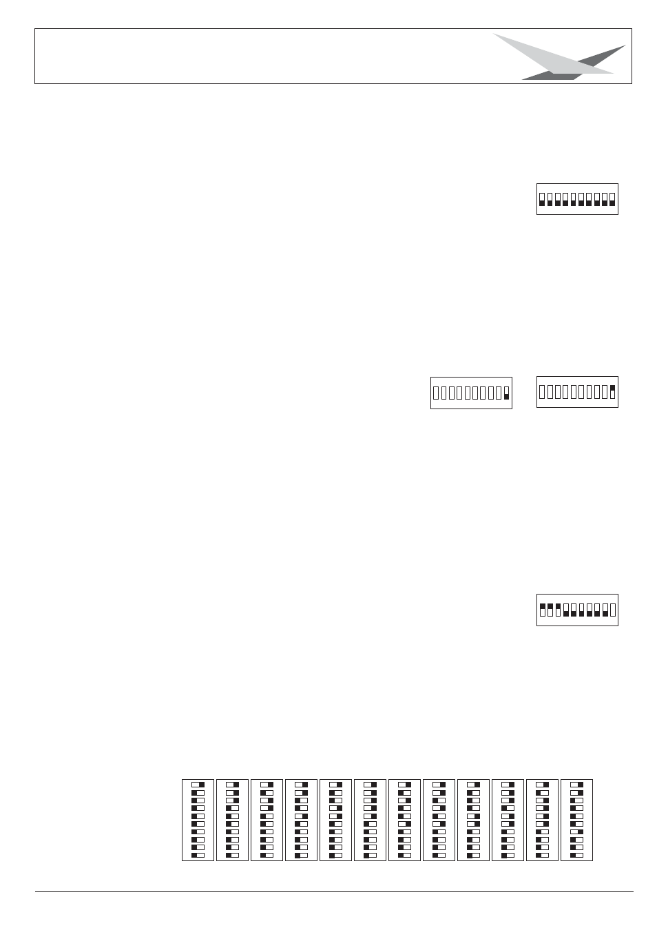
Varyscan No.
1
2
3
4
5
6
7
8
9
10
11
12
DMX address
1
7
13
19
25
31
37
43
49
55
61
67
3. Operation
3.1 DIP switches
The DIP switches are located on the backside of the unit.
The are used to define the different operation modes and
to enter start address.
(See page 16 technical data)
3.2 Select 6 channel or 8 channel mode
3.3 DMX settings
Use DIP switch 1-9 to assign the Varyscan to its address or start channel.
The Varyscan requires either 6 or 8 DMX channes, depending on the
actual mode (see chapter 3.2)
When using the Varyscans in 6 channel mode each unit requires 6 DMX channels.
If the first fixture in line is addressed to starting channel no. 1 the second
unit has to be addressed to channel no. 7. Never occupy one channel twice!
The third Varyscan in line has to be addressed to channel no. 13 and so on.
Example for DMX setting to channel no. “7”
Using the binary system the figure 7 consists of the figures 1+2+3 = 7.
DIP switch one is assigned to figure 1. DIP switch two is assigned to figure 2. DIP
switch three is assigned to figure no. 4. DIP switch four is assigned to figure no.8.
DIP switch five is assigend to figure no. 16 and so on. Switch DIP switch 1,2
and 3 to “on” to assign the Varyscan to start channel no. 7. Leave the rest of
the DIP switches in an “off” position.
Assignment of the first 12 Varyscan in line (6 channel mode)
DIP
ON
12345
6789
1
0
DIP
ON
12345
6789
1
0
12345
6789
1
0
DIP
ON
12345
6789
1
0
DIP
ON
DIP
ON
12345
6789
1
0
DIP
ON
12345
6789
1
0
DIP
ON
12345
6789
1
0
DIP
ON
12345
6789
1
0
DIP
ON
12345
6789
1
0
12345
6789
1
0
DIP
ON
12345
6789
1
0
DIP
ON
DIP
ON
12345
6789
1
0