Anschlüsse empfängermodul, Pinbelegung, Signal – BECKHOFF C9900-A172 Benutzerhandbuch
Seite 10: Pinbelegung 9
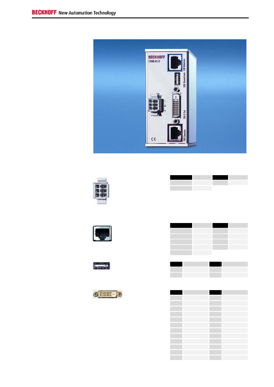
Produktbeschreibung
Anschlüsse Empfängermodul
Anschlüsse des
Empfängermoduls
C9900-A173
X 101
X 102
X 103
X 100
X 104
Pinbelegung
Pin
Signal
Pin
Signal
1
0 V
3
+ 24 V
2
GND
X 100
Stromversorgung
WAGO 734-103/ 037-000
Pin
Signal
Pin
Signal
Gehäuse
Schirm
5
n.c.
1
TD +
6
RD -
2
TD -
7
n.c.
3
RD +
8
n.c.
X 101
USB Extension
RJ-45-Stecker (Ethernet 10/ 100 Mbit)
4
n.c.
Pin
Signal
Pin
Signal
1
5V
3
D +
2
D-
4
GND
X 102
USB Downstream
USB Typ-A Leiterplatten-Montage
(FCI 72309-0030B USB A-Type)
Pin
Signal
Pin
Signal
1
Rx2-
13
Rx3+
2
Rx2-
14
+ 5V DVI
3
GND
15
GND
4
Rx4-
16
HPD
5
Rx4+
17
Rx0-
6
DDC CLK
18
Rx0+
7
DDC DAT
19
GND
8
AV SYNC
20
Rx5-
9
Rx1-
21
Rx5+
10
Rx1+
22
GND
11
GND
23
RxC+
X 103
DVI-D Out
DVI-D 3 X 8-polig digital
(MOLEX 74320-9000 / 74320-9004)
12
Rx3-
24
RxC-
DVI/ USB-Verlängerung C9900-A17x
9