Bronkhorst FLOW-BUS interface Benutzerhandbuch
Seite 7
BRONKHORST
®
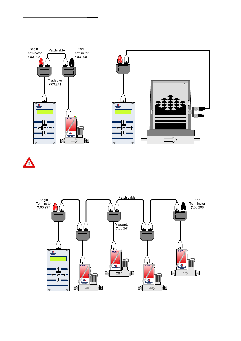
Nachstehend finden Sie einige Beispiele für den Aufbau eines FLOW‐BUS‐Systems. Das Prinzip des FLOW‐BUS‐Systems
ist bei IP40‐ und IP65‐Systemen gleich.
1.
EL‐FLOW mit E‐7000
2.
CORI‐FLOW mit E‐7000
FLOW
mass flow meter/controller
End
Terminator
7.03.321
Y-adapter
7.03.319
Cable RJ45 to M12
Begin
Terminator
7.03.298
FOR LIQUIDS AND GASES
CORI-FLOW
Digital Mass Flow Meter/Controller
BRONKHORST
HI-TEC
FLOW
R
Y-adapter
7.03.241
Seite 7
FLOW‐BUS interface
9.19.024
Das letzte Instrument am Bus benötigt einen Endabschlussstecker (schwarz).
Das erste Modul am Bus (entweder ein E‐7000 Modul für digitale Instrumente oder ein Modul mit
FLOW‐BUS‐Schnittstelle zu einem PC) benötigt einen Anfangsabschlussstecker (rot).
3.
Vier EL‐FLOWs mit E‐7000