33 5.7 wiring diagram, Base pcb, Head pcb – JB-Lighting Varyscan P6 575 HMI Benutzerhandbuch
Seite 32: Ballast, Capacitor, Backside view of pcb head
33
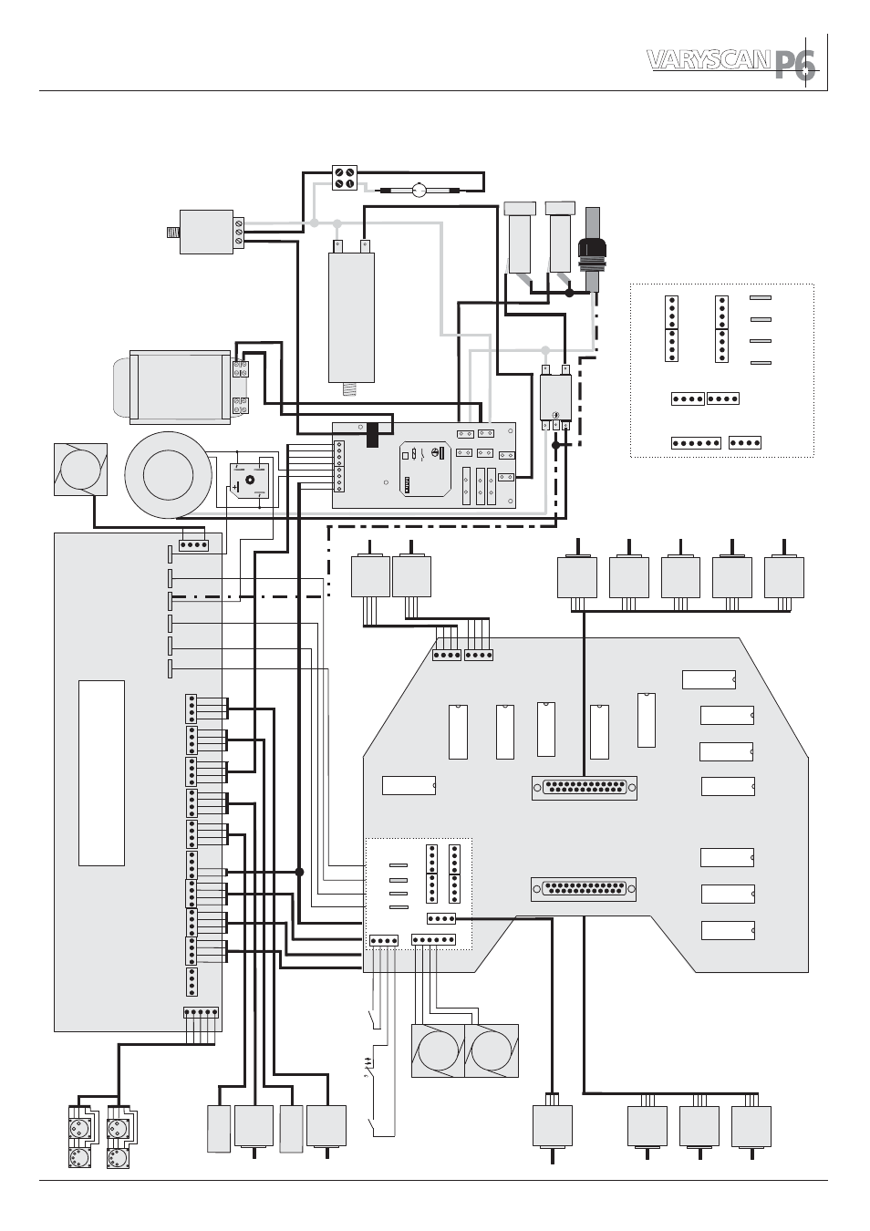
5.7 Wiring diagram
Ballast
240 V
230 V
ZRM (D)
220 V
F
inder
62.22.8.024.430062.22.8.024.4300
16A 250V~
24V AC
HOT IN
HOT OUT
HOT OUT
N IN
N OUT
COMP C1
COMP C1
COMP C2
COMP C2
D
LA
N
Ignitor
Fuse
Fuse
I-LockI-Lock
Main PCB
Fan
Electronic
Lamp
24V~
1,25A
T
5,0A
T
Netzfilter
N
N
L
L
Capacitor
T
ransformer
Head 3
Head 4
Head 1
Head 2
+15V
GND
+32V
+5V
grey
green
yellow
brown
blue
green
yellow
brown
grey
green
blue
brown
white
green
yellow
brown
red fine
red thick
black
yellow
red
blue
yellow
white
black
red
red
red
black
black
yellow
yellow
white
white
Mot PanMot Pan
Fan2
+5 V
+15 V
GND
GND
+32 V
+32 V
Colour 1
Motor
Colour 1
Motor
Colour 2
Motor
Colour 2
Motor
Prism
Motor
Prism
Motor
P-Rot
Motor
P-Rot
Motor
Focus
Motor
Focus
Motor
Shutter
Motor
Shutter
Motor
Mot
Ti
t
Mot
Ti
t
Lamp Rel
Inc Pan
Base PCB
DMX
Fan1
Head1
Head2
Head3
Head4
Inc
T
ilt
Inc
T
ilt
3 red
1 black
2 white
4 brown
5 yellow
+32V
+5V
GND
+15V
HEAD1
HEAD2
HEAD3
HEAD4
Iris Switch
Fan
Fan
Pan
Motor
Pan
Motor
T
ilt
Motor
T
ilt
Motor
Encoder
PCB
Encoder
PCB
Encoder
PCB
Encoder
PCB
Lid Switch
T
e
mp. Switch
T
emp. Switch
Shutter
Motor
Shutter
Motor
Gobo1
Motor
Gobo1
Motor
Gobo rot 2
Motor
Gobo rot 2
Motor
Gobo 2
Motor
Gobo 2
Motor
Shutter
Shutter Motoren
Iris
Gobo 2
Prism
free
P-Rot
Focus
Colour 2
Colour 1
G-Rot 1
Gobo 1
Head 1Head 1
Head 2
Head 3
Head 4
+15V
GND
+32V
+5V
Iris
Head PCB
Backside view of pcb head
free
free
these connectors are
located on the backside
Iris
Motor
Iris
Motor