Connections – Westermo LD-02 Benutzerhandbuch
Seite 11
11
6156-2002
Direction
Circuit no.
CCITT V.24
Signal name
DCE
9-pin D-sub
Circuit no.
O
1
109
DCD/Data Carrier Detect
O
2
104
RD/Received Data
I
3
103
TD/Transmitted Data
I
4
108/2
DTR/Data Terminal Ready
–
5
102
SG/Signal Ground
O
6
107
DSR/Data Set Ready
I
7
105
RTS/Request To Send
O
8
106
CTS/Clear To Send
NC
9
Direction
Circuit
CCITT V.11
no.
Description
Receiver
1
A’ (R+)
Receiver
2
B’ (R-)
Transmitter
3
A (T+)
Transmitter
4
B (T-)
5
1)
Shield
Direction
Circuit no.
Description
Channel 2 Channel 3
Receiver
9
2
R+
Receiver
8
1
R-
Transmitter
7
4
T+
Transmitter
6
3
T-
5
5
1)
Shield
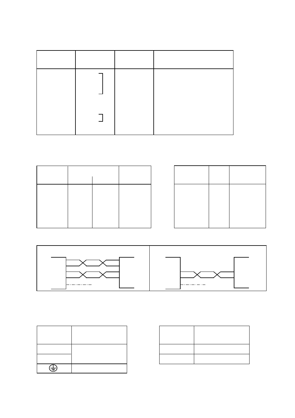
RS-485/422 (channel 4)
Connection
Power supply
no.
1
-Voltage
2
+Voltage
Connection
Power supply
no.
L
115*/230V
N
AC power
PE, Protective Earth
Power connection LD-02 AC
3 position screw-terminal
Power connection LD-02 DC
2 position screw-terminal
Connections
RS-232 (channel 1)
W1, balanced 10mA (channel 2 and 3)
I=input O=output. The LD-02 is a DCE (Data Communication Equipment).
NC=not connected.
* LD-02 115V
RS-485/422 connection (channel 4)
1) If shielded cable is used, connect the shield only at one end to avoid ground loop currents.
LD-02
LD-02
equipment
RS-422/485
Transmitter
Twisted pairs
4-wire
1
2
3
4
5
Shield 1)
A’
B’
A
Receiver
B
A’
B’
A
B
Trans-
mitter
Receiver
equipment
RS-422/485
Transmitter/
Receiver
Transmitter/
Receiver
Twisted pairs
2-wire
3
4
5
A/A’
B/B’
A/A’
B/B’
Shield 1)