Switch settings – Westermo MM-14 Benutzerhandbuch
Seite 9
Advertising
9
6186-2003
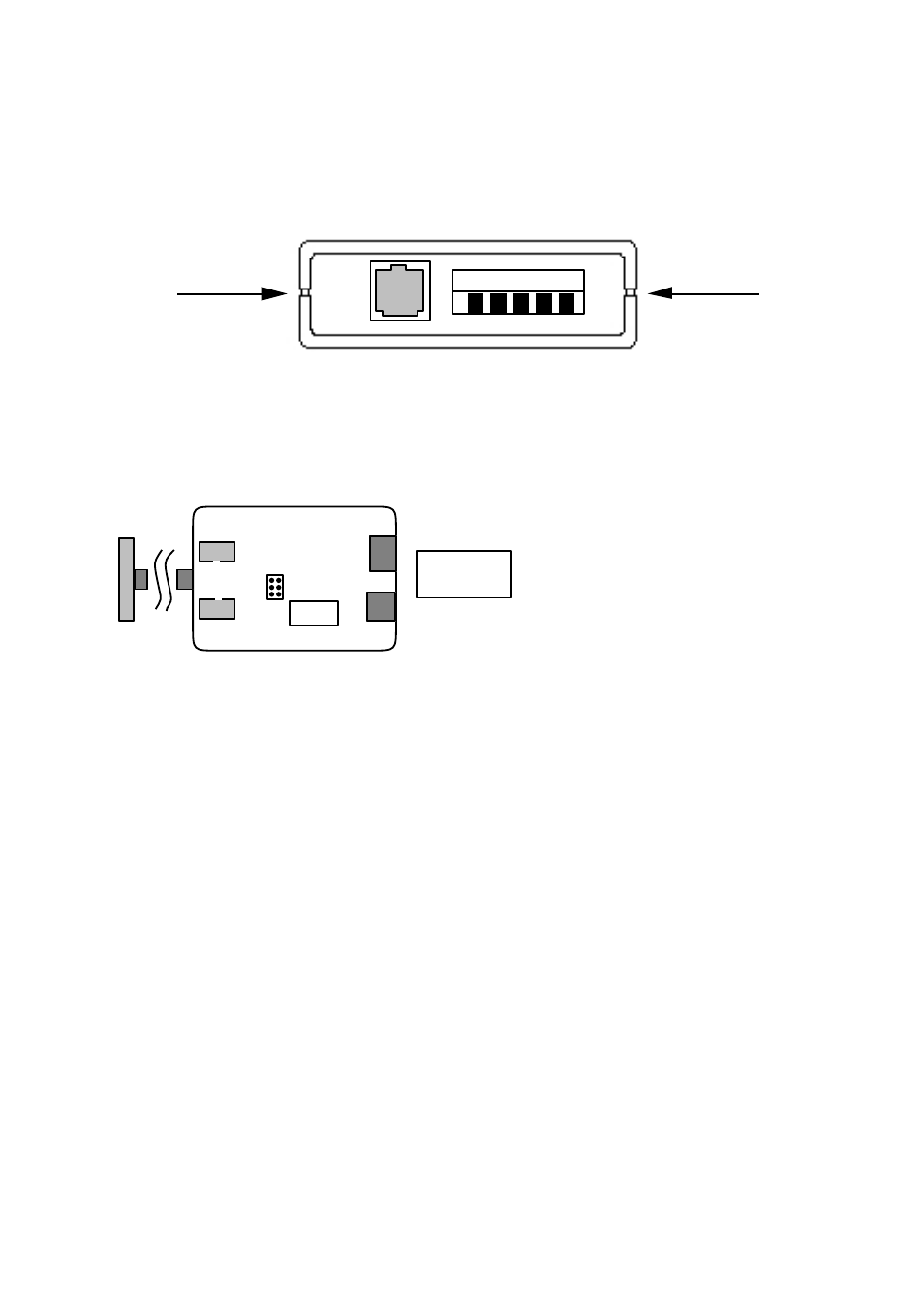
Switch settings
The MM-14 can through different switch settings be adapted to a variety of running con-
ditions. To set the switches, open the plastic case by placing and turning a screw-driver
between top and bottom at the rear of the case.
LINE
1 2 3 4 5
S1
1 2 3 4 5 6
ON
OFF
DTE
DCE
X2
X1
J2
J1
1 2 3
S1
Selection of signal
activating transmitter
(carrier)
Selection of signal
controlling CTS/DTR
X1/X2 Selection of function
DCE/DTE
(The cable is placed in
required connector)
J1/J2
Selection of internal/
external power supply
9/25-pos.
D-sub
On the circuit board the switches has the following location and functions:
Location on circuit board:
Function:
Advertising