Settings, Warning! do not open connected unit, Termination of the line – Westermo TR-23 Benutzerhandbuch
Seite 10: Selection of transmission level, Selection of maximum level, dcd detection
10
6600-2002
Termination of the line
termination
no termination
S1
S1
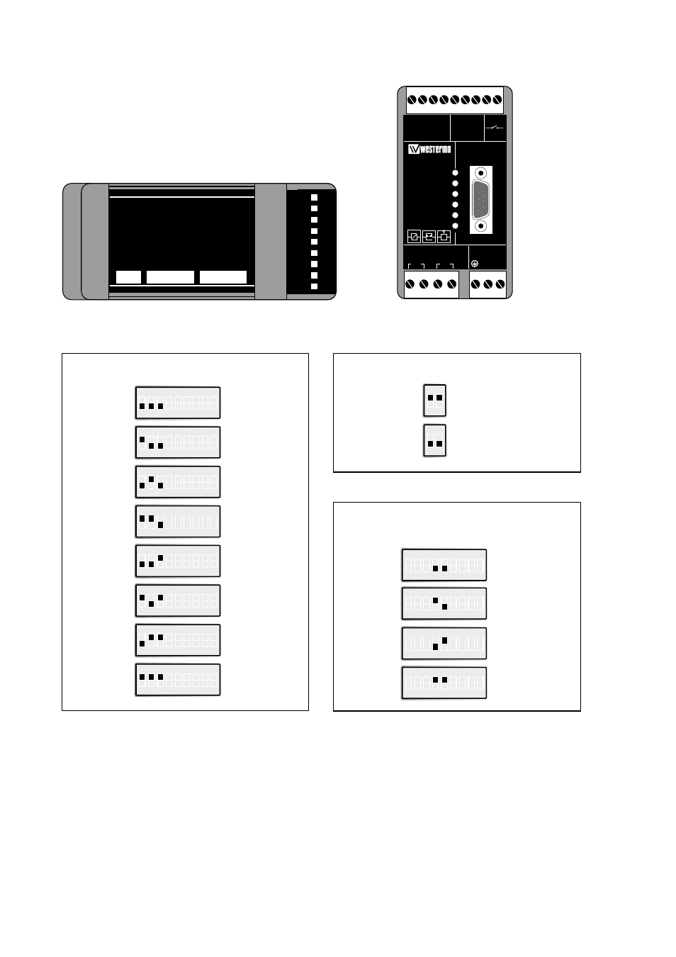
Settings
The TD-23 can be set for a range of different
operating conditions. All settings are made via
the DIP-switches located under the cover on
the modem’s top.
Selection of transmission level
3 dBm
S2
–3 dBm
S2
–6 dBm
S2
–9 dBm
S2
–10 dBm
S2
–12 dBm
S2
–13 dBm
S2
–15 dBm
S2
Selection of maximum level,
DCD detection
–15 dBm
S2
–3 dBm
S2
3 dBm
S2
10 dBm
S2
TD-23
9
R+ R-
T-
SG RD TD
T+
PWR
RD
TD
RTS
CTS
DCD
TX
8 7 6
RS-422/485
RS-232
RELAY
LINE CONNECTION
POWER
5 4 3
V.24/RS-232-C
2 1
RX
N
L
S1:1–2
S3:1–9
S2:1–9
12
3
4
56789
Selection of transmission level specifies the maximum output
power level. The maximum value is 3dBm.
By selecting the higher transmission levels communication over
longer distances can be achieved, but the noise and
disturbance levels will increase. We recommend that you try
your system with the factory default setting first. If disturbances
are detected (faulty characters or other errors) decrease the
power level step by step. If the transmission fails because of a
weak signal the transmission level can be increased step by
step until a satisfactory transmission quality is achieved. Please
note that levels above –9dBm are not allowed on PTT
networks and can only be used on private wires!
Selection of maximum level, DCD detection specifies the
maximum power level the receiver can handle. With the receiver
having a dynamic range of 30dBm, this means that with the level
set to –15dBm the TD-23 will pick up signals in the range
–15dBm to –45dBm.
We recommend that you try your network with the factory
settings. If disturbances are detected (faulty characters or other
errors) decrease the level step by step. If there is no
communication because of a weak signal the receiver sensitivity
can be increased step by step until satisfactory transmission
quality is achieved.
The line should be terminated at the end-points.
ON
1 2 3 4 5 6 7 8 9
ON
1 2 3 4 5 6 7 8 9
ON
1 2 3 4 5 6 7 8 9
ON
1 2 3 4 5 6 7 8 9
ON
1 2 3 4 5 6 7 8 9
ON
1 2 3 4 5 6 7 8 9
ON
1 2 3 4 5 6 7 8 9
ON
1 2 3 4 5 6 7 8 9
ON
1 2
ON
1 2
ON
1 2 3 4 5 6 7 8 9
ON
1 2 3 4 5 6 7 8 9
ON
1 2 3 4 5 6 7 8 9
ON
1 2 3 4 5 6 7 8 9
Warning! Do not open connected unit