Electrical connections, Installation/connection in vhm housing, Screw terminal 2.1 types and specifications – Eneo VHM/H24 PTC-Scheibenheizung Benutzerhandbuch
Seite 6
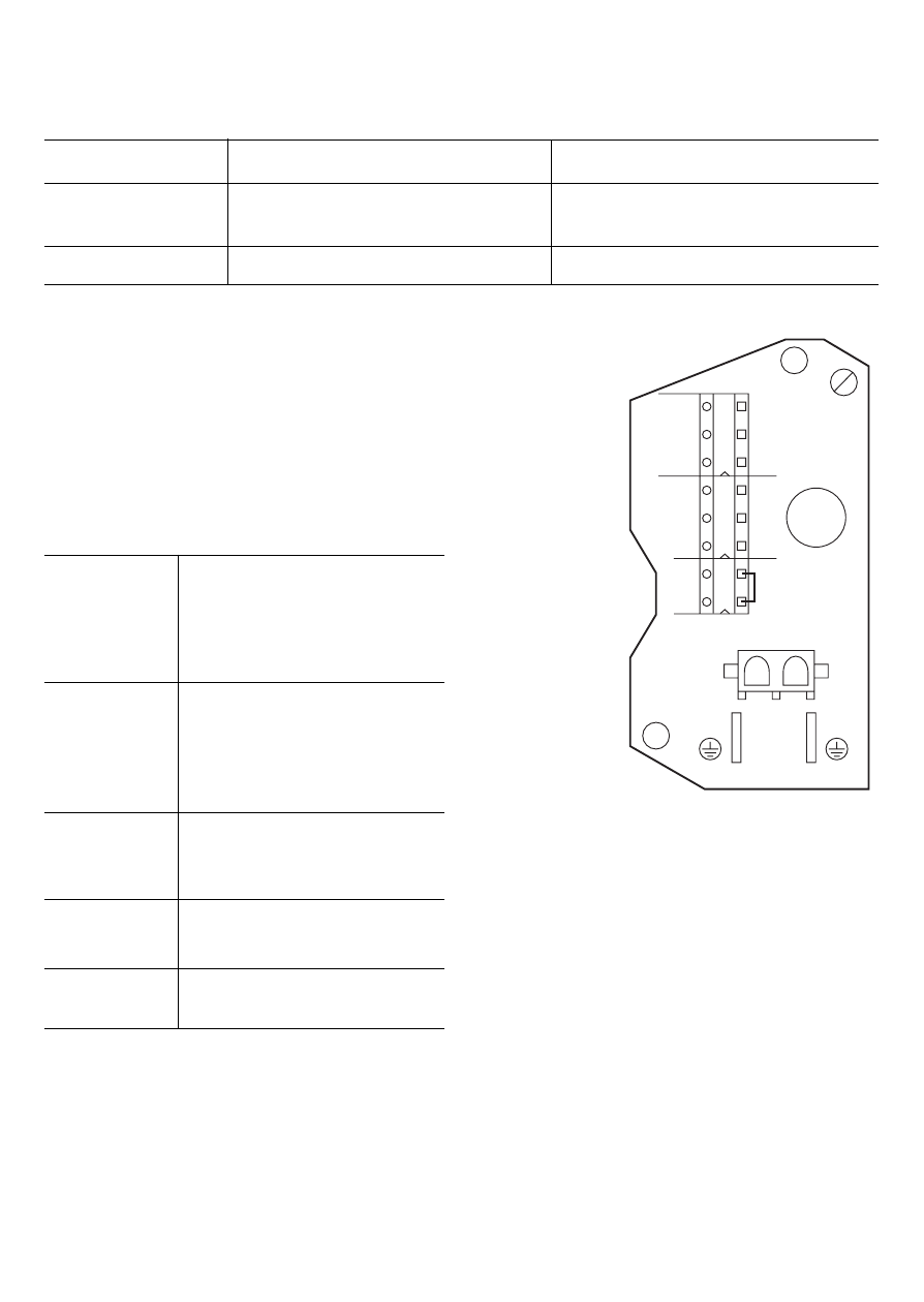
2.2. Electrical connections
(Use mains wires with a core cross-
section of min. 0.75mm
2
and max.
2.5mm
2
).
Terminal 1
Earthing (PE)
Terminal 2
Mains voltage (L1)
Terminal 3
Mains voltage (N)
Terminal 4
Earthing / Camera (PE)
Terminal 5
Camera 230 VAC (N)
Teminal 6
Camera 230 VAC (L1)
Terminal 7
Terminal 8
Connection 9
Heater (2-pole AMP plug
prewired on heatercable)
Conn. 10-11
Plug-in points for earth
connection cable (PE).
}
Replace bridge by using
a thermostat switch
HEATER
1 2 3 4 5 6 7 8
PE L1 N
PE
N
L1
ST
A
T
MAINS
CAMERA THERMO
9
FUSE T1,25A/250V
AC
PE
PE
11
10
2.3. Installation/connection in
VHM housing
Installation has to be made vertical in the
middle plastic part of the rear housing
(see pict. 2). Screw the screw terminal
onto the studs in the cover using the
enclosed self-tapping screws. When
wiring-up, attention must be paid that
the mains connections L1 and N are
connected to the supplied terminals. The
mains ground of the camera must be
connected with the earth terminal on the
screw terminal.
Fig . 1
VHM-KVS
2. Screw terminal
2.1 Types and specifications
Type
Version
Remarks
VHM-KVS
With fuse
For 110 V - 250 V Heaters
T1.25 A / 250 V
VHM-KV
Without fuse
For 12 V - 30 V Heaters