K&M 18822 Third-Tier Stacker for Omega Stands (White) Benutzerhandbuch
Seite 3
18822 Stacker
- for »Omega« Table-style keyboard stands with Stacker 18811
- ideal for a third device
- load bearing weight max. 15 kg
- adjustable in height, depth and inclination
- only suitable for Stacker 18811, NOT for 18813
- Please observe the associated safety notes
- For 18800/18810/18820 and 18811
- Ensure that the connection of the stacker is secure
- Both stackers 1.d are to be placed at the same depth
- Ensure that the rubber rests
1.n
are placed such
-
that the keyboard is securely in place
- In the event of maintenance pay attention to possible risks
- To care for the product, use a damp cloth and a non-
-
abrasive cleaning agent
SAFETY NOTES
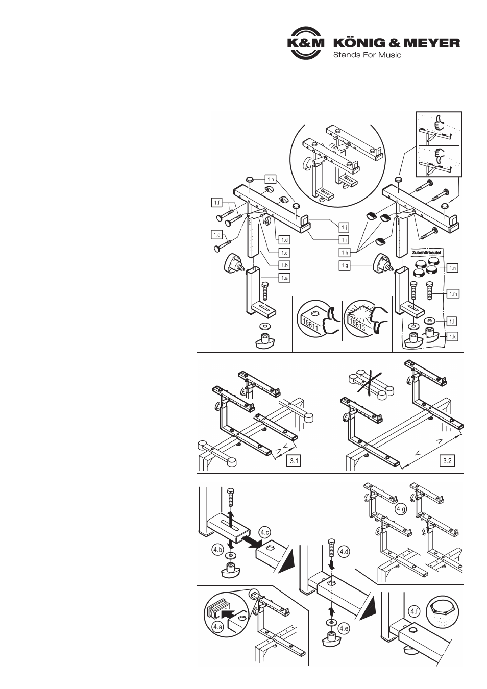
1. COMPONENTS
Stacker 18821 comes completely pre-assembled
and consists of the following individual parts :
1.a
support tube cpl. -
1.b
adjustable tube -
1.c
washer
1.d
support tube -
1.e
carriage bolt M6 x 55 mm with washer
1.f
carriage bolt M6 x 50 mm with washer (2x)
1.g
spring-loaded clamping knob -
1.h
locking nut small, M5 (3x)
1.i
tube cover cap (3x) -
1.j
rubber stop
Accessory bag (1x):
1.k
locking nut large, M6 (2x) -
1.l
washer ø 6,4 mm (2x)
1.m
hexagon bolt M6 x 28 mm (2x) -
1.n
rubber ø 20 x 5 mm (4x)
SETUP INSTRUCTIONS
2. PREPARATION
First the two products:
- »Omega« Table-style keyboard stand,
- 18811 Stacker, adjustable, for »Omega«,
are setup, according to the respective
setup instructions.
3. DETERMINE THE STACKER DISTANCES
Then clarify the distance the 18811 Stacker
is to have
3.1/3.2
. Attach this onto the »Omega«.
3.1
SMALL DISTANCE
3.1
e.g. for laptop:
3.1
- The stacker tubes of »Omega«
3.1
-
the wide stacker stays on the stand
3.2
LARGE DISTANCE
3.2
e.g. for an additional keyboard:
3.2
- The stacker tubes of »Omega« can be
3.2
-
removed due to the “competition” between the
3.2
-
stacker tubes
NOTE:
The distance of the upper stacker equals the lower stacker.
Should the devices require different distance, we
recommend the use of 18819 on the bottom and 18824
on the top.
4. MOUNT 18822 STACKER
The only difference between the stackers is the position of
the clamping nuts
1.h
. They can be applied on the inside or
the outside (see Section 5).
4.a
Remove the back tube cap for 18811
4.b
Remove the screws
1.k.l.m
from support tube
4.c
Place the strut in the open tube
4.d
Place the hexagon screw from the top
4.d
until it is level in the hole
4.e
Place the U-disk and nut from below and tighten
4.f
Check to ensure that the nut is tight:
4.f
- The hexagon head
1.m
is level and tight in the
4.f
-
drill hole
4.f
- The locking nut
1.k
has been tightened as far
4.f
-
as it will go
4.f
- The support tube
1.a
is secure and can no longer be
4.f
-
moved by hand
4.g
Mount the second stacker tube in the same manner.
4.g
Both stacker tubes must be adjusted to the same depth.
Thank you for choosing this product. The instructions provide directions to all of the important setup and handling steps. We recommend you keep these
instructions for future reference.
1. COMPONENTS
3. DETERMINE THE STACKER DISTANCES
4. MOUNT 18822 STACKER
2. PREPARATION