K&M 18822 Third-Tier Stacker for Omega Stands (White) Benutzerhandbuch
Seite 4
USAGE NOTES / FUNCTION
FAULT-FINDING (F) and
REPAIR (R)
F: The stacker 18822 cannot be fastened
F:
R: Wrong base, i.e. Stacker 18813 must
F: R:
be replaced with Stacker 18811
F: The stacker 18822 wobbles
F:
R: Tighten the clamping nuts
1.g.h.k
F:
R: Ensure that the hexagon is properly
F:
B:
placed in the opening (hole)
4.f
F:
R. Check that the screw connection of the
F:
B:
»Omega« and stacker 18811 is tight
F: The Keyboard sits inclined or wobbles
F:
R: The same applies for both stackers
F:
B:
(18811, 18822):
F:
R:
- synchronously adjust the front stops
F:
R:
of the stackers
6.3
,
F:
R:
- Ensure that the right and left support
F:
R:
are at the same height
F:
R:
- also always set the same angle of
F:
R:
inclination
F:
R:
- Place rubber pads so that keyboards
F:
R:
rest on them
9. DIMENSIONS
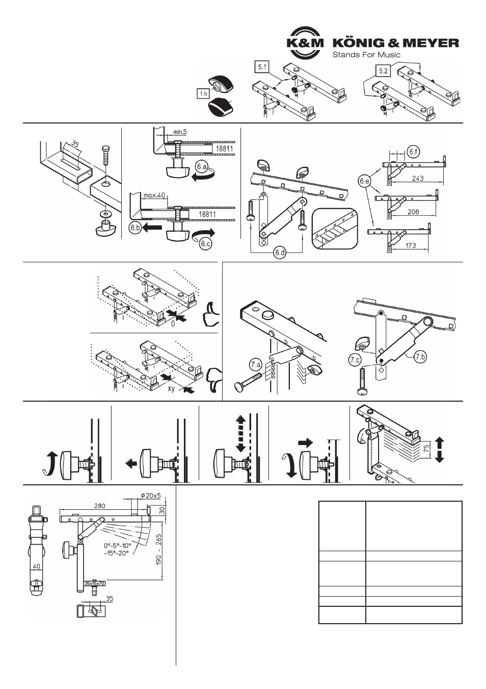
5. POSITION OF THE OPERATING ELEMENTS (laterally locking nuts)
Both stacker parts function in the same manner.
They do differ in the position of the operating elements
1.h
,
which are mounted on the right side of one attachment and
on the left side of the other.
There are two installation options,
i.e. one can select between:
5.1
locking nuts located on the inside
5.2
locking nuts located on the outside
TECHNICAL DATA
Material
Tubes:
Steel, powder coating, black
Screws, washers:
Steel galvanized
Plastic parts:
PA, PE, TPE, black
Load
max. 15 kg
Dimensions
Stacker:
Width : 40 mm, Depth: 280 mm
Clear height: 190-265 mm
Weight
2.6 kg
Verpackung
L x W x D: 300 x 320 x 90 mm
Accessories
(optional)
18824 Controller keyboard tray
KÖNIG & MEYER
GmbH & Co. KG
Kiesweg 2, 97877 Wertheim, www.k-m.de
18822-019-55/76/91 Rev.05/02/01 03-80-374-00 4/21
6. SUPPORT DEPTH
8. HEIGHT ADJUSTMENT
6.1
STEPLESS
MOVING
The support tube
1.a
has
a 35 mm long slot for step-
less adjustment of the support.
6.a
Loosen the clamping nut a bit...
6.b
... and place the support tube
1.a
in the desired position,
6.c
Tighten the locking nut
1.k
6.3
SYNCHRONOUS
STOP
The front part of the
stacker tube should
be the same, i.e.
parallel to the cross
tube of the
keyboard stand.
8.a
Loosen the spring-
loaded clamping knob
1.g
somewhat
8.b
Pull the handle until
the locking bolt is no
longer in position
8.c
Adjust the
support arm
up or down
8.d
Place the lock bolt in is the
desired hole and let it click
into place then tighten the
spring-loaded clamping
knob
8.d
The height of the
8.d
support arms can be
8.d
adjusted -7 positions-
8.d
each step is
12.5 mm.
support
tube
from
below
6.2
DEPTH - PRESET
(0-35-70 mm)
6.d
Completely dismantle both screw connections of the support tube.
6.e
Position the support as desired (3 variants)
6.f
NOTE: The distance between the mounted screws
6.f
NOTE:
is always two holes
7. INCLINATION ANGLE (0° - 5° - 10° - 15° - 20°)
7.a
Disassemble the screw connection
7.b
Adjust U-strut as required (5 variants)
7.c
Lock the U-strut and tube with the carriage bolt and secure with the locking nut