7 wiring diagram, Base pcb, Head pcb – JB-Lighting Varyscan P3 250 HTI Benutzerhandbuch
Seite 32: Ballast 1, Capacitor, Ignitor fan, Backside view of pcb head
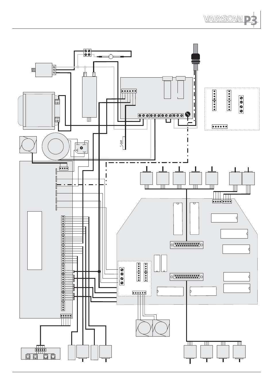
5.7 Wiring diagram
Ballast 1
50Hz
60Hz
Ph
D
LA
N
Ignitor
Fan
Capacitor
T
ransformer
Head 3Head 3
Head 4
Head 1Head 1
Head 2
+15V
GND
+32V
+5V
grey
green
yellow
brown
blue
green
yellow
brown
blue
brown
white
green
yellow
brown
red fine
red thick
black
yellow
red
black
red
black
Mot Pan
Fan2
Fan2
+5 V
+15 V
GND
GND
+32 V
+32 V
Colour 1
Motor
Colour 1
Motor
Colour 2
Motor
Colour 2
Motor
Prism
Motor
Prism
Motor
P-Rot
Motor
P-Rot
Motor
Focus
Motor
Focus
Motor
Shutter
Motor
Shutter
Motor
Mot
Ti
t
Mot
Ti
t
Lamp Rel
Inc Pan
Base PCB
DMX
Fan1
Head1
Head2
Head3
Head4
Inc
T
ilt
3 red
1 black
2 white
4 brown
5 yellow
+32V
+5V
GND
+15V
HEAD1
HEAD2
HEAD3
HEAD4
Pan
Motor
Pan
Motor
T
ilt
Motor
T
ilt
Motor
Encoder
PCB
Encoder
PCB
Encoder
PCB
Encoder
PCB
Temperature
switch
Temperature
switch
Shutter
Motor
Shutter
Motor
Gobo 1
Motor
Gobo 1
Motor
Goborot 2
Motor
Goborot 2
Motor
Gobo 2
Motor
Gobo 2
Motor
Shutter Motors
Jp1
Iris
Head 1
Head 2
Head 3
Head 4
+15V
GND
+32V
+5V
Iris
Motor
Iris
Motor
Head PCB
Backside view of PCB head
These connectors are
located on the backside
Fuse
Fuse
Electronic
Gobo 1
Gobo 2
Grot
Prot
Focus
Shutter
Color 1
Color 2
Lamp
Fan
Fan
2 A
T
220V device: 3,15
AT
1
15V device: 4A
T
33