Mod cvm 144 c2-currents – CIRCUTOR CVM144 Series Benutzerhandbuch
Seite 12
----- Netzanalysator CVM-144 ------ --- Seite Nr. 11
4.3.3.- Modul Erschluss- und Nullleiterstrom (770 572, 770 575 und
770578)
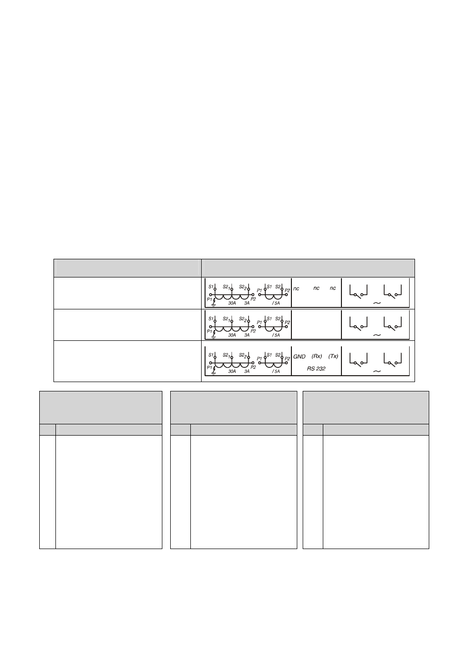
Beschreibung
Etiquette für Klemmen Erweiterungkarte
Mod CVM 144 -C2-Currents
(Code: 7 70 572)
13
14
15
16
17
18
19
20
21
22
23
24
250 V
3 A
RL1
RL2
I
N
Mod CVM 144 RS485-C2-Currents
(Code: 7 70 575)
13
14
15
16
17
18
19
20
21
22
23
24
250 V
3 A
R
S 485
(+)
(-)
G
N
D
RL1
RL2
I
N
Mod CVM 144 RS232-C2-Currents
(Code: 7 70 578)
13
14
15
16
17
18
19
20
21
22
23
24
250 V
3 A
RL1
RL2
I
N
Mod CVM 144
C2-Currents
(Code: 7 70 572)
Mod CVM 144
RS485-C2-Currents
(Code: 7 70 575)
Mod CVM 144
RS232-C2-Currents
(Code: 7 70 578)
Nr. Klemmenbeschreibung
Nr. Klemmenbeschreibung
Nr. Klemmenbeschreibung
13
14
15
16
17
18
19
20
21
22
23
24
Erdschlussstrommessung S1
Erdschlussstrommessung S2
(30 A)
Erdschlussstrommessung S2
(3 A)
Nullleiterstrommessung S1
Nullleiterstrommessung S2
Nicht verwendet
Nicht verwendet
Nicht verwendet
Relaisausgang RL2
Relaispol RL2
Relaisausgang RL1
Relaispol RL1
13
14
15
16
17
18
19
20
21
22
23
24
Erdschlussstrommessung S1
Erdschlussstrommessung S2
(30 A)
Erdschlussstrommessung S2
(3 A)
Nullleiterstrommessung S1
Nullleiterstrommessung S2
RS-485 ( GND)
RS-485 ( - )
RS-485 ( + )
Relaisausgang RL2
Relaispol RL2
Relaisausgang RL1
Relaispol RL1
13
14
15
16
17
18
19
20
21
22
23
24
Erdschlussstrommessung S1
Erdschlussstrommessung S2
(30 A)
Erdschlussstrommessung S2
(3 A)
Nullleiterstrommessung S1
Nullleiterstrommessung S2
RS-232 ( GND)
RS-232 ( Rx )
RS-232 ( Tx )
Relaisausgang RL2
Relaispol RL2
Relaisausgang RL1
Relaispol RL1
Hinweise:
•
Zum Messen des Erdschlussstroms müssen Wander der Serie WG xx verwendet
werden. Die Wandler werden je nach gewünschtem Messbereich an den 3 A oder
30 A Eingang angeschlossen.
•
Zum Messen des Nullleiterstroms wird ein Stromwander .../5A verwendet.