Connecting up the dc isolating box 40/60 – Fronius DC-Freischaltbox 40/60 Benutzerhandbuch
Seite 32
10
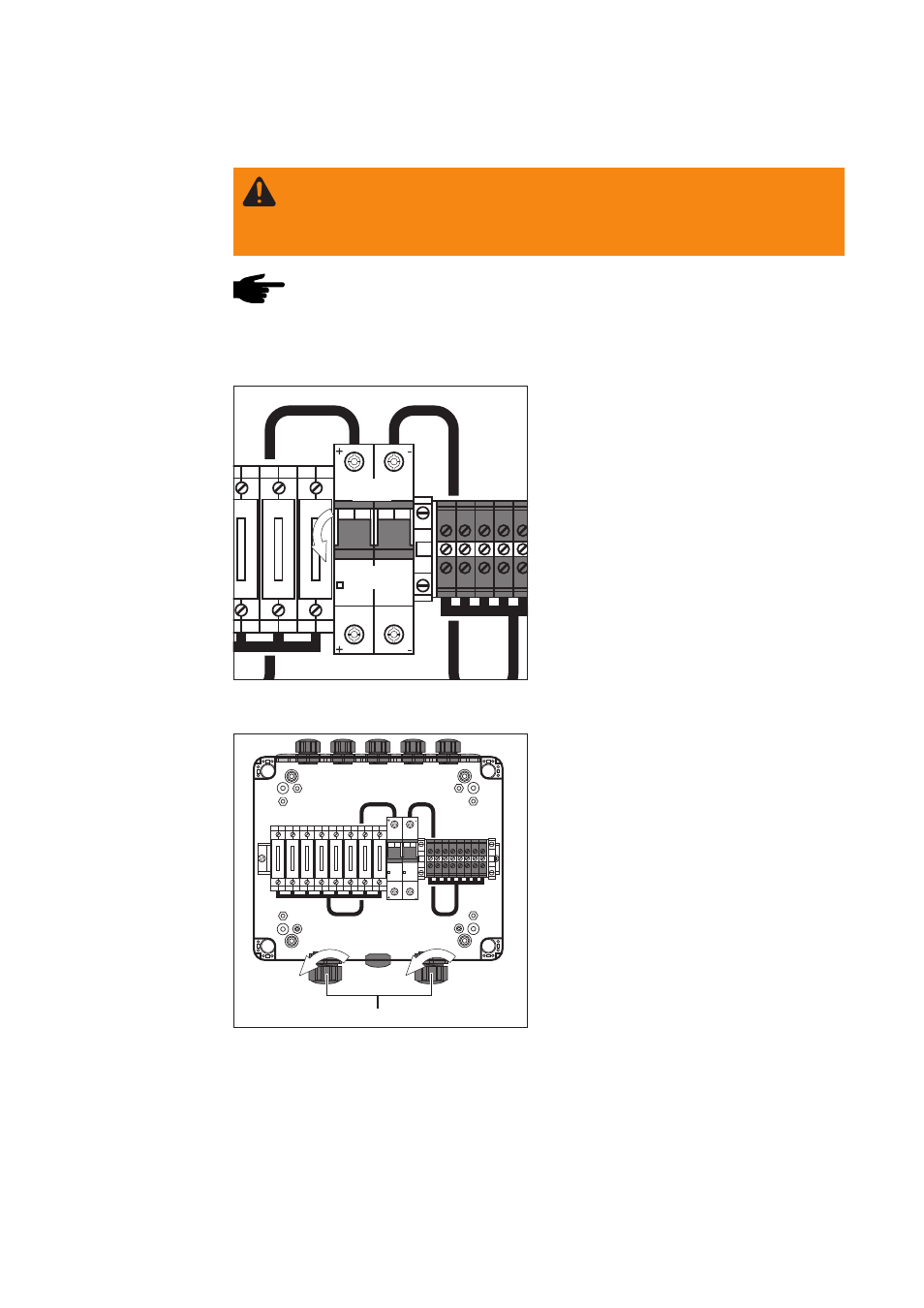
“ON”
“OFF”
WARNING! Work that is not carried out correctly can cause serious injury and
damage. The actions described below may ONLY be carried out by skilled,
Fronius-trained technicians! Read and follow the section headed “Safety rules”
in this operating instructions.
Connecting up the DC isolating box 40/60
NOTE! The ampacity (current-carrying capacity) of the cables used for
connecting up the strings of solar modules, and of the main DC leads to the
inverter, must comply with the applicable national and local Standards!
Fig.9
Switching the DC isolator into the “OFF”
position
Connecting up
the inverter to
the DC isolating
box 40/60
2.
Unscrew the strain relief devices from
the “M25 inverter side” screwed
conduits
Fig.10 Unscrewing the M25 strain relief devices
M25 strain relief devices
Requirements for
connecting up
the DC isolating
box 40/60
1.
Switch the DC isolator into the “OFF”
position