Fronius DC-Freischaltbox 40/60 Benutzerhandbuch
Seite 35
Advertising
13
“ON”
“OFF”
6.
5.
6.
6.
6.
5.
8.
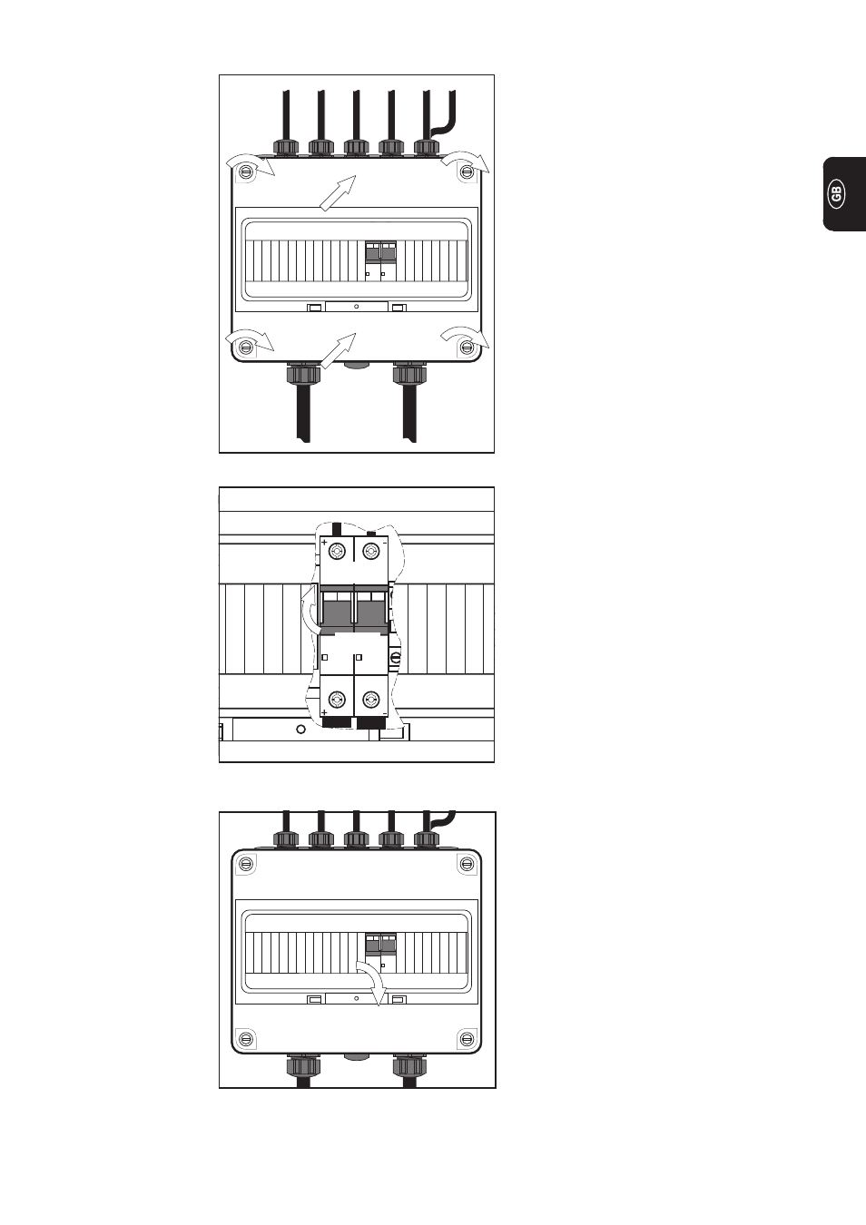
Finishing the job
(continued)
Fig.17 Switching the DC isolator into the “ON”
position
7.
Switch the DC isolator into the “ON”
position (i.e. close the DC isolator) -
the inverter will now be electrically
connected to the solar modules
5.
Place the cover (with its integral
viewing panel) onto the DC isolating
box 40/60 in such a way that the
mounting-cover screws slot into the
recesses
6.
Fix the cover in place by tightening
the mounting-cover screw on the DC
isolating box 40/60
Fig.16 Mounting the cover and viewing panel
8.
Close the viewing panel
Fig.18 Closing the viewing panel
Advertising
Dieses Handbuch ist für die folgenden Produkte bezogen werden: