Varyscan micro 150hti, Operation, 1 dip switches – JB-Lighting Varyscan Micro 150 HTI Benutzerhandbuch
Seite 15: 2 8 bit and 16 bit mode, 3 dmx settings
Varyscan MICRO 150HTI
15
JB-lighting Lichtanlagentechnik GmbH Sallersteigweg 15 D-89134 Blaustein 07304-9617-0
3. Operation
3.1 DIP switches
The DIP switches are located at the base of the Varyscan Micro 150HTI.
The are used to define the different operation modes.
-1
-2
-4
-8
-16
-32
-64
-128
-256
-Mode
DIP
ON
12345
6789
1
0
3.2 8 bit and 16 bit mode
Pan and tilt movement can either be controlled by 8 bit or
16 bit mode (depending on the lighting control desk in use).
Operating the Varyscan in 16 bit mode result in a very
precise movement of pan and tilt. Projection of images on
long distances will be much more accurate in 16 bit mode.
If the lighting control desk is only able of working in 8 bit
mode, never use 16 bit mode on the Varyscan.
The result might be vice versa.
JB-lighting control consols can operate in the following modes:
JB-lighting DMX-Controller
8Bit
JB-lighting ScanControl
8Bit
JB-lighting LICON 1
16Bit
-1
-2
-4
-8
-16
-32
-64
-128
-256
-Mode
DIP
ON
12345
6789
1
0
-1
-2
-4
-8
-16
-32
-64
-128
-256
-Mode
8bit mode
16 bit mode
DIP switches 10
OFF
DIP switches 10
ON
3.3 DMX settings
Use DIP switch 1-9 to assign the Varyscan to its address or start channel.
In 8 bit mode 6 channels are required. In 16bit the MICRO 150HTI requires 8 channels per unit.
The binary system is used to enter the start channel for each unit.
When using the Varyscans in 8 bit mode each unit requires 6 DMX channels. If the first
fixture in line is addressed to starting channel no. 1 the second unit has to be addressed
to channel no. 7. Never occupy one channel twice! The third Varyscan in line has to be
addressed to channel no. 13 and so on.
Example for DMX setting to channel no. “7”
Using the binary system the figure 7 consists of the figures 1+2+4 = 7.
DIP switch one is assigned to figure 1. DIP switch two is assigned to figure 2. DIP
switch three is assigned to figure no. 4. DIP switch four is assigned to figure no.8.
DIP switch five is assigend to figure no. 16 and so on. Switch DIP switch 1,2
and 3 to “on” to assign the Varyscan to start channel no. 7. Leave the rest of
the DIP switches in an “off” position.
-1
-2
-4
-8
-16
-32
-64
-128
-256
-Mode
DIP
ON
12345
6789
1
0
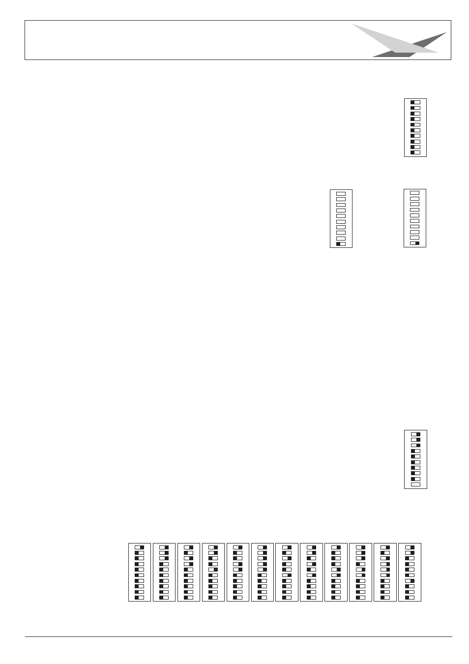
Assignment of the first 12 Varyscan in line (6 channel mode / 8 bit)
DIP
ON
12345
6789
1
0
Varyscan No.
1
2
3
4
5
6
7
8
9
10
11
12
DMX Address
1
7
13
19
25
31
37
43
49
55
61
67
DIP
ON
12345
6789
1
0
DIP
ON
12345
6789
1
0
DIP
ON
12345
6789
1
0
DIP
ON
12345
6789
1
0
DIP
ON
12345
6789
1
0
DIP
ON
12345
6789
1
0
DIP
ON
12345
6789
1
0
DIP
ON
12345
6789
1
0
DIP
ON
12345
6789
1
0
DIP
ON
12345
6789
1
0
DIP
ON
12345
6789
1
0
DIP
ON
12345
6789
1
0