Westermo TR-23 Benutzerhandbuch
Seite 12
12
6600-2002
O
1
109
DCD/Data Carrier Detect
O
2
4
104
RD/Received Data
I
3
3
103
TD/Transmitted Data
NC
4
–
5
5
102
SG/Signal Ground
O
6
107
DSR/Data Set Ready
I
7
105
RTS/Request to Send
O
8
106
CTS/Clear to Send
NC
9
Signal description
Terminal connection (DCE)
(RS-232-C/V.24, 9-pole D-sub, female alt. 9-pole screw terminal)
I = input O = output NC = not connected
Potential free
contact
The connection to the
potential free contact
(relay) is made by
position 1 and 2 in the
9-pole screw terminal.
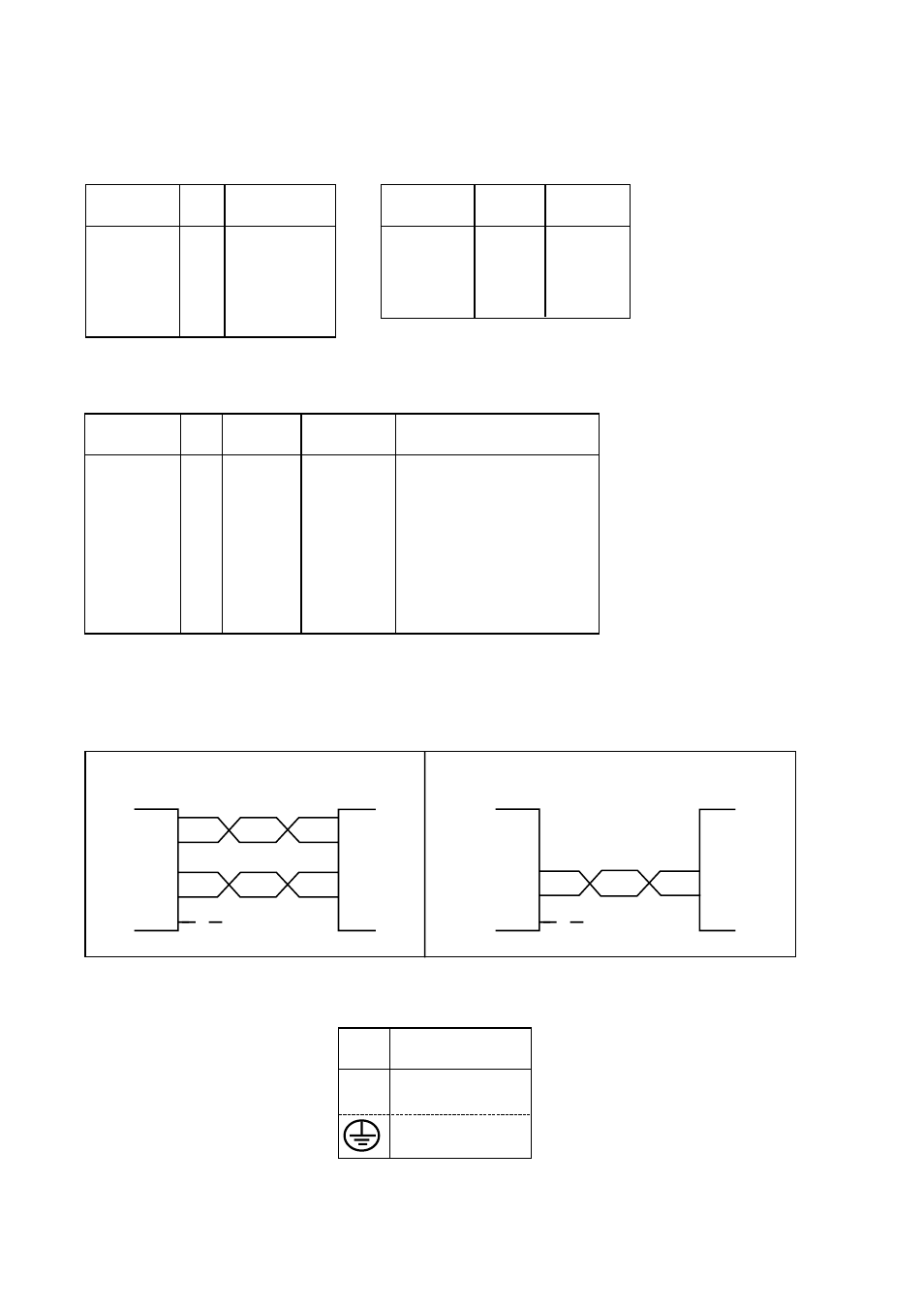
RS-422/485 connection
(9-pole screw terminal)
Line connection
(4-pole screw terminal)
2-wire lines are
connected to pins
1 and 2
Direction
Pin
no.
Screw-
terminal
CCITT V.24
Description
Direction
No.
Description
Receiver
9
A’ (R+)
Receiver
8
B’
(R-)
Transmitter
7
A
(T+)
Transmitter
6
B
(T-)
5
Shield
Direction
Pin no.
line
Description
Receiver
3
R
Receiver
4
R
Transmitter
1
T
Transmitter
2
T
Connections TD-23
RS-485/422 connection
1) NB if shielded cable is used it should be connected only at one extreme in order to avoid
circulating earth currents in the shield.
4-wire
2-wire
9
8
7
6
5
7
6
5
A’
B’
A
B
A
B
A’
B’
Receiver
Receiver
A/A’
B/B’
B/B’
A/A’
Twisted pairs
Twisted pairs
TD-23
TD-23
Transmitter
Transmitter
RS-422
equipment
RS-485
equipment
Transmitter/
Receiver
Transmitter/
Receiver
Shield 1)
Shield 1)
N
115V*/230V
L
AC power
PE/Protective Earth
Power connection (AC)
(3-pole screw terminal)
* TD-23 115V
No.
Power
supply