HEIDENHAIN IK 215 Benutzerhandbuch
Seite 8
8
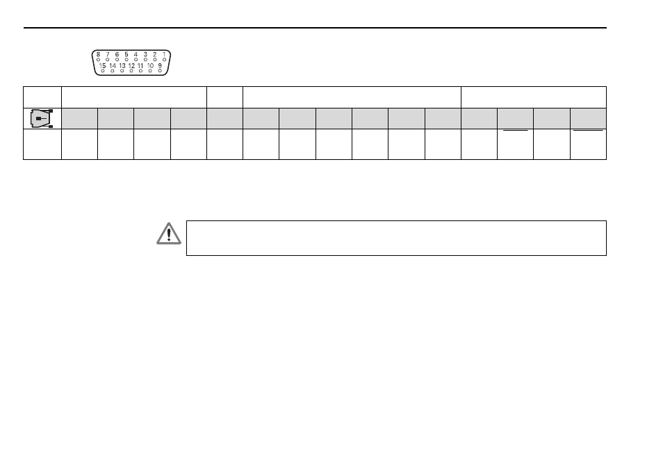
Pin layout of the IK 215
Connection for the encoder
The encoder is connected to the input X1.
The pin layout of the 15-pin D-sub female connector is as follows:
Power supply
Incremental signals
Absolute position values
4
12
2
10
6
1
9
3
11
14
7
5
13
8
15
U
P
Sensor
U
P
0 V
Sensor
0 V
Internal
shield
A+
A –
B+
B –
R+
R –
DATA
DATA CLOCK CLOCK
Shield on housing; U
P
= Power supply
Sensor: The sensor line is connected in the encoder to the respective the power supply. The voltage at the encoder can be tested over sensor
lines and, if required, adjusted.
Vacant pins or wires must not be used!
The power supply of the encoder (pin 4) is adjustable and switchable per software. To avoid damage to
the encoder, ensure that the correct supply voltage is selected. Remember also that the encoder must
not be connected or disconnected while under power.
IK 215
English