Montage der hauptkontakte, Main contact assembly – Multi-Contact MA206 Benutzerhandbuch
Seite 5
Advanced Contact Technology
www.multi-contact.com
5 / 12
2
3
4
5
1
L
K
X
Sichtloch
Sight hole
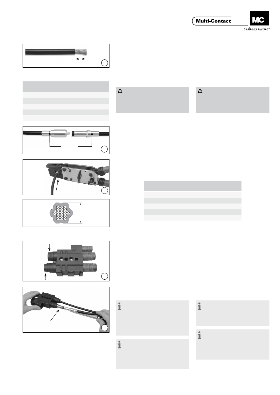
Montage der Hauptkontakte
Vorbereitung der Leitungen
(ill. 1)
Leitung entsprechend dem Quer-
schnitt auf Mass L abisolieren.
Presszange mit entsprechendem
Pressgesenk bestücken (Tab.1).
Main contact assembly
Preparation of cables
(ill. 1)
Depending on the conductor cross-
section, strip insulation to dimension
L. Equip crimping tool with appropri-
ate die (Tab.1).
Achtung
Minimal zulässiger Leitungs-
durchmesser Ø 13 mm!
Maximal zulässiger Leitungs-
durchmesser Ø 20,5 mm!
Attention
Minimal admissible cable diame-
ter Ø 13 mm!
Maximal admissible cable diame-
ter Ø 20,5 mm
Crimpen der Kontakte
(ill. 2)
Einzelleiter in die Crimphülse des Kon-
taktes einführen bis diese im Sichtloch
erscheinen.
Crimping the contacts
(ill. 2)
Insert the wire into the contact crimp-
ing sleeve until it appears in the sight
hole.
(ill. 3)
Crimpvorgang gemäss MA226 durch-
führen. Der Leiter darf sich nach dem
Crimpvorgang nicht aus der Crimphül-
se herausziehen lassen. (Kontrolle!)
(ill. 3)
Crimping process according to
MA226. After Crimping, the cable may
not be removed from the crimp barrel.
(Control!).
Einbauen der Kontakte
(ill. 4)
Leitungstüllen am Isoliergehäuse ent-
sprechend dem Leitungsdurchmesser
kürzen. Leitungsdurchmesser sind auf
der Leitungstülle angegeben.
Installing the contacts
(ill. 4)
Shorten the cable grommet on the
insulated housing to suit the cable
diameter. Cable diameters are stated
on the cable grommet.
(ill. 5)
Kontakte in die Kontaktkammern
des Isoliergehäuses vorstecken. Bei
Buchsenkontakten wird zusätzlich ein
Einbaukonus (K) auf den Kontakt auf-
gesetzt. Kontakteinbauwerkzeug am
rückseitigen Bund des Kontaktes an-
setzen und Kontakt bis zum Anschlag
eindrücken.
Hinweis:
Um den Einpressvorgang durch-
zuführen, müssen die Kontakte vor
dem Einsetzen in das Isoliergehäuse
in Ethanol oder Industriealkohol
getaucht werden.
Achtung: kein Fett verwenden!
Hinweis:
Je nach Steifigkeit der verwen-
deten Leitung können die Kontakte
ohne Einbauwerkzeug montiert wer-
den. Der Einbaukonus für Buchsen-
kontakte wird dennoch benötigt.
(ill. 5)
Pre-mount the ends of the contacts
into the contact chambers of the in-
sulated housing. In the case of socket
contacts, also place an insertion cone
(K) onto the contact. Set contact inser-
tion tool against the back shoulder of
the contact and press the contact in
upto the stop.
Note:
Before pressing the contacts into
the housing, be sure to dip them in
Ethanol or industrial alcohol.
Warning: do not use any grease!
Note:
If the stiffness of the cable permits
it, it may be possible to install the
contacts without an insertion tool.
But the insertion cone is required for
socket contacts in any case.
Tab. 1
Kabelquerschnitt
Conductor cross-section
L±1
(mm)
Pressgesenk
Crimping die
25mm²
16
TB11
35mm²
21
TB13
50mm²
27
TB14,5
70mm²
27
TB17
95mm²
29
TB20
Pressgesenk
Crimping die
max. Kontrollmass X
max. control dimension X
TB11
8.8
TB13
10.2
TB14.5
11.4
TB17
13.4
TB20
16.4
Tab. 2