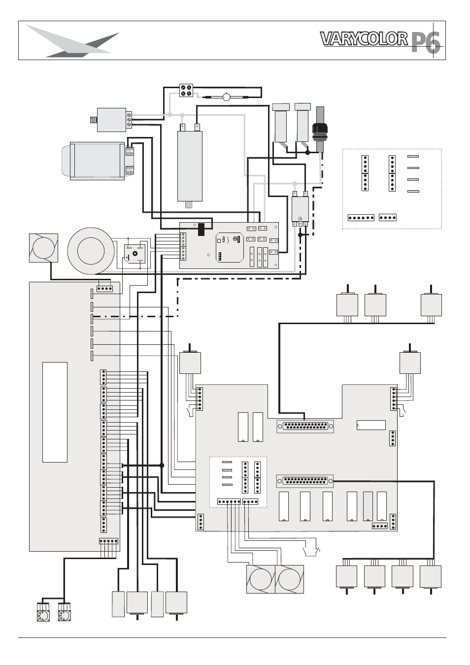
6 wiring diagram, Base pcb, Head pcb – JB-Lighting Varycolor P6 575 HMI Benutzerhandbuch
Seite 34: Cap acitor 1 cap acitor 1 ballast, Ignitor, Trans- former t rans- former, Backside view of pcb head
34
JB-lighting Lichtanlagentechnik GmbH Sallersteigweg 15 D-89134 Blaustein Telefon +49 (0)7304-9617-0
5.6 Wiring diagram
F
inder
62.22.8.024.4300
16A
250V~
16A
250V~
24V
A
C
24V
AC
HOT IN
HOT IN
HOT OUT
HOT OUT
N IN
N IN
N OUT
N OUT
COMP C1
COMP C1
COMP C2
COMP C2
D
LA
N
Ignitor
Fuse
Fuse
240
V
240
V
230
V
230
V
ZRM
(D)
ZRM
(D)
220
V
220
V
I-LockI-Lock
Main
PCB
Main
PCB
Fan
Electronic
Lamp
24V~
1,25
A
T
5,0
A
T
mainsfilter
N
N
L
L
Cap
acitor
1
Cap
acitor
1
Ballast
T
rans-
former
T
rans-
former
Head
3
Head
3
Head
4
Head
4
Head
1
Head
1
Head
2
Head
2
+15V
GND
+32V
+5V
grey
green
yellow
brown
blue
green
yellow
brown
grey
green
blue
brown
white
green
brown
red fine
red thick
black
yellow
red
black
red
red
black
black
yellow
yellow
Mot
P
an
Mot
Pan
Fan2
+5
V
+5
V
+15
V
+15
V
GND
GND
+32
V
+32
V
+32
V
+32
V
SHUTTER
Motor
SHUTTER
Motor
SHUTTER
Motor
SHUTTER
Motor
EFFECT
Motor
EFFECT
Motor
Zoom
Motor
2
Zoom
Motor
2
Mot
Ti
t
Mot
Ti
t
Lamp
Rel
Lamp
Rel
Inc
Pan
Inc
Pan
Base
PCB
DMX
Fan1
Head1
Head2
Head3
Head4
Inc
T
ilt
Inc
T
ilt
3red
1black
2white
4brown4brown
5yellow
+32V
+15V
Head1
Head2
Head3
Head4
Fan
Fan
Pan
Motor
Pan
Motor
T
ilt
Motor
T
ilt
Motor
Encoder
PCB
Encoder
PCB
Encoder
PCB
Encoder
PCB
Zoom
Motor
1
Zoom
Motor
1
Y
ellow
Motor
Y
ellow
Motor
Cyan
Motor
Cyan
Motor
Magent
a
Motor
Magent
a
Motor
Color
Motor
Color
Motor
Backside view of pcb head
FOCUS 1
FOCUS 1
these connectors are
located on the back-
side
these connectors are
located on the back-
side
Head
1
Head
1
Head
2
Head
2
Head
3
Head
3
Head
4
Head
4
+15V
GND
+32V
+5V
Head PCB
G-Rot
2
G-Rot
2
G-Rot
2
G-Rot
2
CT
O
YELLOW
G-Rot
2
G-Rot
2
G-Rot
2
G-Rot
2
G-Rot
2
G-Rot
2
CY
AN
MAGENT
A
MAGENT
A
COLOR
SHUTTER
FOCUS
2
FOCUS
2
EFFECT
FOCUS
2
FOCUS
2
FOCUS
1
FOCUS
1
FA
N
FA
N
FAN
Lid
Switch
Lid
Switch
Switch
Zoom
Switch
Zoom
Switch
Zoom
Switch
Zoom
+5V
GND
yellow
T
e
mperature
Switch
T
emperature
Switch