HUBER+SUHNER Splicing fiber tray into ODR Benutzerhandbuch
Seite 3
Assembly Instruction / Montageanleitung
FiberTray II into NGR
FiberTray II in NGR
Created by: LiSA R&D
DOC-0000351880
Rev: C
www.hubersuhner.com
uncontrolled copy
3 / 8
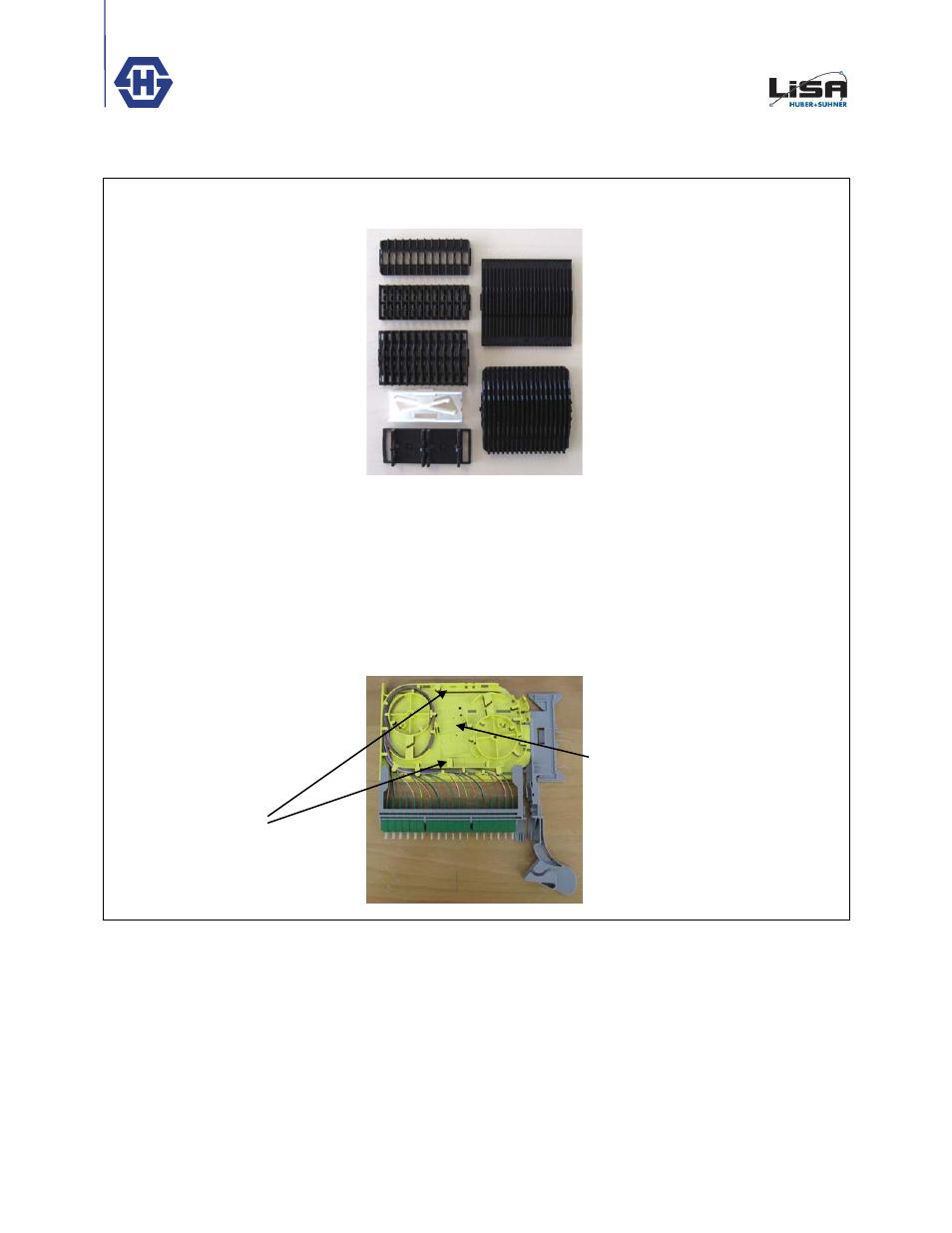
Assembly of Splice Protection
Holders
The following holder types are
available for the FiberTray.
A: 12 pcs. Shrink 3.0mm
(84147301)
B: 24 pcs. Shrink 1.8mm
(84123618)
C: 36 pcs. Shrink 1.8mm
(84142487)
D: 4 pcs. Fibrlok II or Splitter
(84089021)
E: Fan-out Holder (84081432)
F: 24 pcs. Sandwich (84103969)
G: 36 pcs. Sandwich
(84103960)
The Splice Holders A, B, C, E, F and
G can be snapped directly in the
FiberTray
The Holder D can be snapped in in
two positions. In the first position, the
downholder first has to be removed.
Splice Holder positions in the
FiberTray.
D
Einbau von Spleissschutzhaltern.
Folgende Halter sind für das
FiberTray verfügbar
A: 12 fach Schrumpf 3.0mm
(84147301)
B: 24 fach Schrumpf 1.8mm
(84123618)
C: 36 fach Schrumpf 1.8mm
(84142487)
D: 4 fach Fibrlok II oder Splitter
(84089021)
E: Fan-out Halter (84081432)
F: 24 fach Sandwich (84103969)
G: 36 fach Sandwich (84103960)
Die Halter A, B, C, E, F und G
können direkt im FiberTray
eingeschnappt werden.
Der Halter D kann an zwei Positionen
im FiberTray eingeschnappt werden.
Bei der einen Position muss der
Niederhalter vorher entfernt werden.
Spleisshalter Positionen im
FiberTray.
A, B, C, E, F, G
A
B
C
D
E
F
G