Optibox16 – HUBER+SUHNER OTB16 Benutzerhandbuch
Seite 4
Created by: FO R&D
www.fiberinthehome.com
4
DOC
-
0000401065
uncontrolled copy
Rev: A
Assembly Instruction / Montageanleitung
OptiBox16
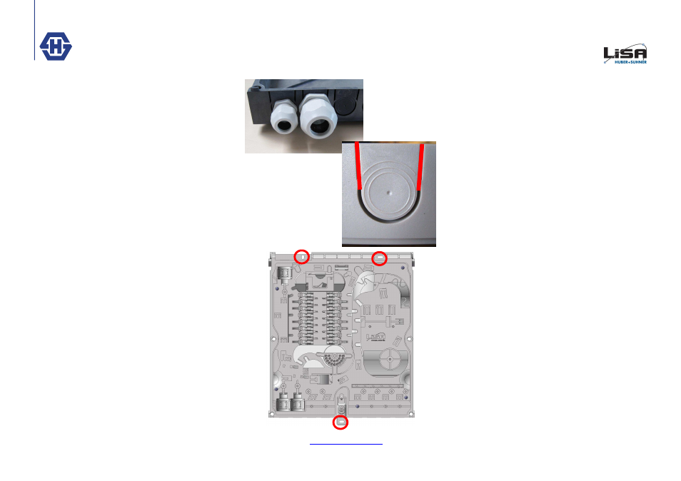
III. Preparing cable entries (U
-
Shape grom-
mets and cable glands)
At the bottom side of the box you can open 8 holes for
cable entries or exit with U
-
Shape grommets or cable
glands. If you are using cable glands you have to drill
the correct hole. You can use M16 and M25 cable
glands. If you are using M25 glands please take care
that the outer dimension is max. 33.5mm.
If you are using U
-
Shapes, you have to make a cut
according to the red line on the picture. After that you
can break out easily.
III. Kabeleinführung vorbereiten
(Kabelverschraubung und U
-
Shapes)
An der Unter
-
und Oberseite der Base können 8 Öff-
nungen für ein
-
oder austretende Kabel mittels U
-
Shape Kabeldurchführungen oder Kabelverschrau-
bung gemacht werden. Für Kabelverschraubungen
muss mit einem Stufenbohrer ein passendes Loch ge-
bohrt werden. Eine Zentrierhilfe ist in der Mitte der Ein-
führungsposition vorhanden. Es können Kabelver-
schraubungen M16 und M25 eingebaut werden. Bei
M25 muss auf eine schmale Bauform geachtet werden
max. Aussendurchmesser der Kabelverschraubung
oder der Mutter ist 33.5mm.
Werden U
-
Shapes benutzt, muss entsprechend dem
roten Strich auf dem Foto gesägt werden. Der Rest
des U
-
Shapes lässt sich danach sehr einfach ausbre-
chen.
IV. Wandmontage
Zur Wandmontage der Box die Base an die vorgese-
hene Wand halten. Anschliessend die drei Loch Po-
sitionen auf der Wand markieren. Danach können die
Löcher gebohrt und die Base an der Wand befestigt
werden.
IV. Wall mounting
For wall mounting, put the Box on the wall, adapt the
three fixing hole point to the wall. After that you can
drill the holes and fix the box on the wall.