Multi-Contact MA246 Benutzerhandbuch
Seite 5
Advanced Contact Technology
Advanced Contact Technology
8 / 20
www.multi-contact.com
www.multi-contact.com
9 / 20
7
8
10
9
N
11
12
13
14
15
B
(ill. 7)
Befestigen Sie das Hilfswerkzeug
durch entsprechende Befestigungsele-
mente (z�B� Winkelschienen)� Nutzen
Sie dazu die 3-seitig angebrachten
Befestigungsbohrungen je nach Gege-
benheiten�
(ill. 7)
Fix the auxiliary tool by means of
suitable retaining elements (e�g� angle
irons). Use the fixing holes provided
on 3 sides as appropriate�
Hinweis:
Die Befestigungselemente sind
nicht im Lieferumfang enthalten.
Note:
Retaining elements not supplied.
Vorbereiten der Flachbandlei-
ter
(ill. 8)
Schneiden Sie die Flachbandleiter auf
eine Länge von 61 mm zu. Sie können
Flachbandleiter bis zu einer Breite von
6.5 mm montieren.
Preparing the ribbon conduc-
tors
(ill. 8)
Cut the ribbon conductors to a length
of 61 mm. You can fit ribbon conduc-
tors with a width of up to 6.5 mm.
Einsetzen der Paneldose in
das Hilfswerkzeug
PV-WZ-JB/LC
(ill. 9)
Der Arretierbolzen „N“ muss sich in
der vorgespannten Ausgangsposition
befinden, bevor die Paneldose in das
Montagewerkzeug eingesetzt wird�
Inserting the junction box in
the auxiliary tool
PV-WZ-JB/LC
(ill. 9)
The locking pin “N” must be in the
spring-loaded starting position before
the junction box is inserted in the as-
sembly tool�
(ill. 10)
Um die Paneldose in das Montage-
werkzeug einzusetzen, drücken Sie die
Paneldosenaufnahme etwas zurück�
Dadurch schiebt sich der Arretierstift
nach hinten (Druckfeder gespannt)�
Legen Sie die Paneldose ein� Drücken
Sie die beiden Anschlusskabel in die
Federklammer des Kabelhaltebügels�
Bewegen Sie die Paneldosenaufnah-
me nach dem Einlegen der Paneldose
wieder etwas nach vorne (Ausgangs-
position)� Dadurch kann der Arretier-
stift in die dafür vorgesehene Öffnung
der Paneldose einfahren (Druckfeder
gespannt)�
(ill. 10)
To insert the junction box in the as-
sembly tool, the junction box recep-
tacle is pushed back slightly so that
the locking pin is moved backwards
(pressure spring under tension)� In this
position the junction box is inserted
and the two connecting cables are
pressed into the spring clips of the
cable holder� After inserting the junc-
tion box, the junction box receptacle
is again moved slightly forwards
(starting position) so that the locking
pin can enter the opening provided for
it in the junction box (pressure spring
de-tensioned)�
Montage der Flachbandleiter
Fitting the ribbon conductors
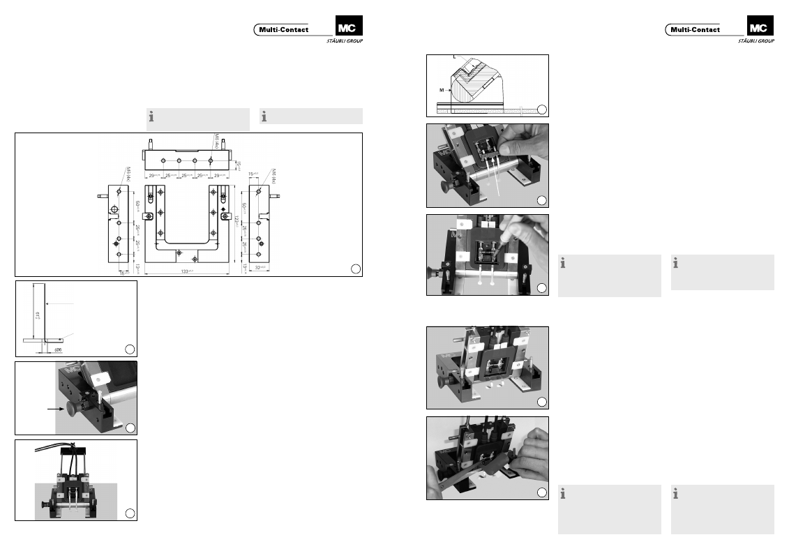
(ill. 11)
Spannen Sie die Flachbandleiter „M“
leicht straff (evtl� mit Pinzette und
Schraubendreher) über die Stirnseite
des Gehäuses und legen Sie sie bis
zum Kontaktteil „L“ mit dem aufge-
brachten Lötzinn an�
(ill. 11)
Lightly stretch the ribbon conductors
“M” over the front of the housing (e�g�
with tweezers and screwdriver) and
take them as far as the contact part
“L” with solder applied�
(ill. 12)
Fixieren Sie sie die Flachbandleiter mit
dem lose mitgelieferten PV-Bügel „B“,
d�h� drücken Sie den PV-Bügel in die
dafür vorgesehene Aussparung in der
Paneldose bis zum Anschlag ein�
(ill. 12)
Fix the ribbon conductors with the PV
clip “B” which is supplied loose, i�e�
press the PV clip as far as it will go
into the recess provided in the junc-
tion box�
(ill. 13)
Verlöten sie die Flachbandleiter mit
dem PV-Kontaktteil� Löttemperatur:
320 °C – 450 °C (bei Verwendung des
empfohlenen Flussmittels)
(ill. 13)
Solder the ribbon conductors to the
PV contact part� Soldering tempera-
ture: 320 °C – 450 °C (if the recom-
mended flux is used).
Hinweis:
Es ist unbedingt notwendig,
zusätzlich Lötflussmittel zuzuführen.
MC empfiehlt die Verwendung des
Lötflussmittels 950E
(Kester, www.kester.com).
Note:
It is absolutely necessary to apply
additional solder flux. MC recom-
mends the use of solder flux 950E
(Kester, www.kester.com).
Montage der Paneldose auf
das PV-Modul
Mounting the junction box on
the PV module
(ill. 14)
Nachdem Sie die Flachbandleiter
angelötet haben, schwenken Sie die
Paneldosenaufnahme nach vorne, bis
der vorgespannte Arretierbolzen in
einer seitlichen Bohrung der Paneldo-
se einrastet� Dadurch ergibt sich eine
Schrägstellung der Paneldosenaufnah
me von ca. 70° zur Waagrechten.
(ill. 14)
After you have soldered on the ribbon
conductors, pivot the junction box
receptacle forwards until the spring-
loaded locking pin engages in a hole
in the side of the junction box� The re-
ceptacle is then at an angle of approx�
70° in relation to the horizontal.
(ill. 15)
Die Flachbandleiter sind in dieser
Position entspannt, so dass ein Frei-
raum zwischen der Klebefolie und den
Flachbandleitern entsteht� Jetzt kön-
nen Sie die rote Schutzfolie mit Hilfe
der weissen Abzugslaschen von der
Klebefolie abziehen� Um die Schutzfo-
lie vollständig zu entfernen, schneiden
Sie sie einseitig, möglichst mittig, ein�
(ill. 15)
In this position the ribbon conduc-
tors are slack, thus creating a space
between the adhesive foil and ribbon
conductors� You can now pull off the
red protective film by means of the
white tabs of the adhesive foil� In
order to completely remove the pro-
tective film, make a cut into it on one
side, preferably in the middle�
Hinweis:
Halten Sie die Zeit zwischen dem
Abziehen der Schutzfolie und dem
Aufbringen der Dose auf das Panel
so kurz wie möglich, damit der Kleb-
stoff nicht durch Staub, Fingerab-
drücke etc. verunreinigt wird.
Note:
Keep the time between the re-
moval of the protective film and the
application of the junction box to the
panel as short as possible, in order to
prevent soiling of the adhesive with
dust, fingerprints etc.
Flachbandleiter
Flat ribbon conductor
PV-Modul
PV module