Multi-Contact MA246 Benutzerhandbuch
Seite 7
Advanced Contact Technology
Advanced Contact Technology
12 / 20
www.multi-contact.com
www.multi-contact.com
13 / 20
21
22
23
24
20
50 mm
57 mm
Für den Fall, dass Sie auf das MC
Hilfswerkzeug verzichten und ein eige-
nes Verfahren / eigenes Hilfswerkzeug
zur Anwendung bringen möchten, soll
ihnen ill� 19 als Orientierung dienen�
Ferner beachten Sie bitte unbe-
dingt folgende Hinweise:
• Die Länge der Kontaktbändchen
muss auf das Montageverfahren
abgestimmt sein.
• Nach der Montage der Paneldo-
se dürfen die Kontaktbändchen
keine Berührung mit der Klebe-
folie haben. Der Abstand muss
mindestens 1 mm betragen.
• Stellen Sie sicher, dass die Bänd-
chen im Doseninnern keinen
Kurzschluss verursachen.
For the event that you proceed
without the MC assembly tool and
instead use your own process or your
own tool, ill� 19 is intended to serve as
a guide�
It is also essential to observe the
following:
• The length of the contact rib-
bons must be adapted to the
assembly procedure.
• After the mounting of the
junction box, there must be no
contact between the contact
ribbons and the adhesive foil.
There must be a space of at
least 1 mm
• Make certain that the ribbons do
not cause a short circuit inside
the box.
Aufbringen der Paneldose
Applying the junction box
2) Silikon-Applikation
(Dow Corning PV 804)
2) Silicone application
(Dow Corning PV 804)
Drücken Sie die Paneldose nach dem
Aufsetzen kurz an (kurzer leichter
Druck auf die Rückseite der Vorrich-
tung reicht)�
Die Montage der Paneldose mit dem
Hilfswerkzeug PV-W Z-JB/LC Silikon
auf das PV-Modul wird auf den folgen-
den Seiten ausführlich beschrieben�
Zudem befinden sich in der Lieferung
Vorfixierungsstreifen, die Sie bitte an
eine geeignete Stelle anbringen� Die
folgenden Illustrationen zeigen dies
exemplarisch�
Briefly apply pressure to the junction
box after placing in position� Short,
light pressure on the back of the tool
is sufficient).
The fixing of the junction box to the
PV module with the auxiliary tool
PV-W Z-JB/LC Silicone is described
in detail on the following pages� The
junction box is also supplied with
prefixing strips. Please apply these
in an appropriate location, as shown
by way of an example in the following
illustrations�
Einrichten des Hilfswerkzeugs
PV-WZ-JB/LC Silikon
Setting up the auxiliary tool
PV-WZ-JB/LC Silicon
Montagewerkzeug auf das Modul
aufsetzen und in Position bringen�
Place auxiliary tool on the module and
bring into position�
(ill. 20)
(ill. 20)
Hinweis:
Der Abstand zwischen Kontakt-
bändchenaustritt und dem Rand des
Montagewerkzeugs muss 50 ± 1 mm
betragen
Note:
The distance between the exit
point of the contact ribbon and the
edge of the assembly tool must be
50 ± 1 mm
Befestigen Sie das Hilfswerkzeug
durch entsprechende Befestigungsele-
mente (z�B� Winkelschienen)� Nutzen
Sie dazu die 3-seitig angebrachten
Befestigungsbohrungen je nach Gege-
benheiten�
Fix the auxiliary tool by means of
suitable retaining elements (e�g� angle
irons). Use the fixing holes provided
on 3 sides as appropriate�
Hinweis:
Die Befestigungselemente sind
nicht im Lieferumfang enthalten.
Note:
The retaining elements are not
supplied.
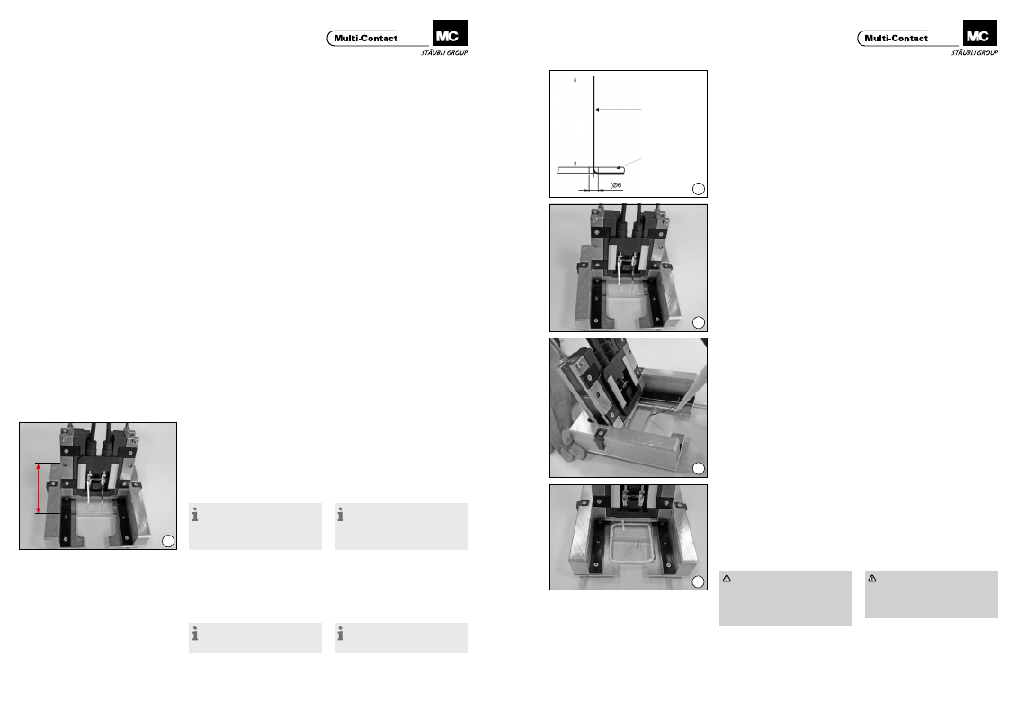
Vorbereiten der Flachbandleiter
Preparation of the flat ribbon con-
ductors
(ill. 21)
Flachbandleiter sollen eine Länge
von 57 mm haben bzw. auf die Länge
zugeschnitten werden� Es können
Flachbandleiter bis zu einer Breite von
6,5mm montiert werden�
(ill. 21)
Flat ribbon conductors should have
a length of 57 mm or be cut to this
length� Ribbon conductors with a
width of up to 6.5mm can be fitted.
Einsetzen der Paneldose in das
Hilfswerkzeug PV-WZ-JB/LC Sili-
kon
Inserting the junction box in the
auxiliary tool PV-WZ-JB/LC Silicon
(ill. 22)
Die Paneldose wird per Hand in die
Vorrichtung eingeklemmt und die
beiden Anschlusskabel in die Feder-
klammer des Kabelhaltebügels einge-
drückt�
(ill. 22)
The junction box is placed by hand
into the cavity and the two connect-
ing cables are pressed into the spring
clips of the cable holder�
(ill. 23)
Hilfsvorrichtung ausrichten und fixie-
ren� Dabei müssen die Markierungen
auf der Vorrichtung mit dem Austritt
der Kontaktbändchen fluchten.
(ill. 23)
Align the auxiliary tool and fix in place.
The markings on the gauge must be in
alignment with the ribbon conductors
exit point�
(ill. 24)
Silikonstrang (ca. Ø 3 mm) entspre-
chend der Geometrie-Schablone
aufbringen�
Darauf achten, dass die Kontaktbänd-
chen nicht mit dem Silikon in Berüh-
rung kommen�
(ill. 24)
Apply the silicone (strand diameter
approx. 3 mm) in accordance with
the geometry of the template� It is im-
portant to note that the Silicone must
not come in contact with the ribbon
conductors�
Montage der Flachbandleiter
Fitting the flat ribbon conductors
Achtung
Alle folgenden Schritten müssen
innerhalb von 5 Minuten bewerk-
stelligt werden, um eine Trock-
nung und somit Härtung des
Silikons zu vermeiden
Attention
All the following steps must be
done within 5 Minutes� This is
important to avoid the drying of
the Silicone�
Flachbandleiter
Flat ribbon conductor
PV-Modul
PV module