Multi-Contact MA246 Benutzerhandbuch
Seite 6
Advanced Contact Technology
Advanced Contact Technology
10 / 20
www.multi-contact.com
www.multi-contact.com
11 / 20
17
18
19
16
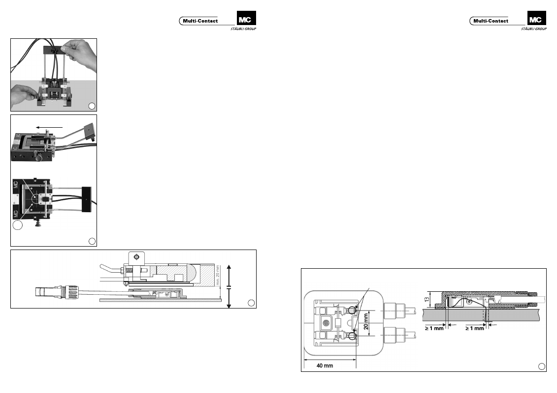
Verschieberichtung
Direction of movement
Positionierkreuz für Druckstempel
Positioning cross for pressure pad
Druckstempel max. Ø 30 bei einer Positionier
genauigkeit von ± 1
Pressure pad max. Ø 30 with a positioning
accuracy of ± 1
(ill. 16)
Ziehen Sie den Arretierbolzen „N“ zu-
rück, d�h� ziehen Sie ihn nach aussen
und drehen Sie ihn bis zum Anschlag
gegen den Uhrzeigersinn�
Halten Sie während des Zurückzie-
hens des Arretierbolzens die Paneldo-
senaufnahme fest und schwenken Sie
diese in die waagrechte Position�
(ill. 16)
Withdraw the locking pin “N”, i�e�
pull it towards the outside and turn it
anticlockwise as far as it will go� While
withdrawing the pin, hold the junc-
tion box receptacle and move it into a
horizontal position�
(ill. 17)
Schieben Sie die Paneldosenaufnah-
me in Pfeilrichtung bis zum Einrasten�
Nun befindet sich die Paneldose ca.
2mm über der Oberfläche des PV
Moduls�
Zum Aufsetzen der Paneldose ver-
wenden Sie einen z�B� zylindrischen
Druckstempel� Positionieren Sie das
Zentrum des Druckstempels mög-
lichst genau auf dem Schnittpunkt des
Positionierkreuzes� Drücken Sie mit
dem Druckstempel das Innenteil min-
destens 5 Sekunden lang nach unten�
Wenden Sie dafür eine Anpresskraft
von 700 – 800 N auf (Die Federkraft
des Innenteils beträgt 100 N).
(ill. 17)
Press the junction box receptacle in
the direction of the arrow until it clicks
in place�
The junction box is now approximately
2mm above the surface of the PV
module�
To fix the junction box, use an (e.g. cy-
lindrical) press� Position the centre of
the press as exactly as possible on the
intersection point of the positioning
cross� With the press, apply pressure
of 700 – 800 N to the inner part for at
least 5 seconds (the spring pressure of
the inner part is 100 N).
(ill. 18)
Nachdem der Setzvorgang beendet
ist, bringen Sie den Druckstempel
wieder in seine Ausgangsposition�
Heben Sie nun das komplette Hilfs-
werkzeug senkrecht nach oben an
bzw� senken Sie das PV-Modul senk-
recht nach unten ab� Der Anhebe-
bzw� Absenkweg muss mindestens
20 mm betragen, damit die Paneldose
aus ihrer Aufnahme befreit ist�
Erst jetzt dürfen Sie das komplette
Hilfswerkzeug oder das PV-Modul
seitlich wegschwenken�
(ill. 18)
When the pressing operation is com-
pleted, return the press to its starting
position� Now move the complete
auxiliary tool vertically upwards or
the PV module vertically downwards�
The raising or lowering distance must
be at least 20 mm in order to com-
pletely release the junction box from
its holder� Only now may you pivot
the complete assembly tool or the PV
module away to the side�
Wichtiger Hinweis zur Klebe-
verbindung
Nach dem korrekten Aufsetzen der Pa-
neldose benötigt die Klebeverbindung
ca. 72 Stunden zum vollständigen
Abbinden� Erst nach dieser Zeit hat
die Klebeverbindung die geforderte
Dichtigkeit und darf der Umgebungs-
feuchtigkeit ausgesetzt oder Reini-
gungsarbeiten unterzogen werden�
Normales Handling (Transport etc�) ist
schon kurz nach der Klebung möglich�
Auch nach Ablauf der 72 h ist darauf
zu achten, dass die Anschlussdo-
sen keinem übermässigen und/oder
dauerhaftem Druck/Schub durch
horizontales oder vertikales Stapeln
der Module oder Zug/Druck durch
die Anschlusskabel ausgesetzt sind�
Bitte beachten Sie dazu auch die
Sicherheitshinweise auf Seite 2 dieser
Montageanleitung�
Important note on the adhesi-
ve bond
After the junction box has been cor-
rectly fixed in place, the adhesive
bond needs approximately 72 hours
to cure completely� Only after this
time does the bond have the neces-
sary impermeability so that it can be
exposed to environmental moisture
or subjected to cleaning operations�
Normal handling (transport) is already
possible a short time after bonding�
Even after 72 hours have expired, care
must be taken that the junction boxes
are not subjected to excessive and/or
continuous pressure or other forces
as a result of the horizontal or vertical
stacking of the modules or from ten-
sion / pressure of connecting cables�
Please refer to the safety instructions
on page 2 of this assembly instruc-
tions�
Hinweise zur Montage der
Paneldose auf das PV-Modul
ohne Zuhilfenahme des MC
Hilfswerkzeugs PV-WZ-JB/LC
Wir empfehlen für die sachgerechte
Montage der Paneldosen die Verwen-
dung des Hilfswerkzeugs
PV-WZ-JB/LC� Dieses Hilfswerkzeug
wurde speziell entwickelt, um bei der
Montage die richtige Position der Pa-
neldose relativ zum Austritt der Kon-
taktbändchen zu erzielen. Nur durch
die genaue Einhaltung der auf den
vorangegangenen Seiten beschrie-
benen Vorgehensweise und der dort
angegebenen Einrichtmasse kann eine
korrekte Montage garantiert werden�
Notes on the fixing of the
junction box on the PV modu-
le without the use of the MC
auxiliary tool PV-WZ-JB/LC
For the correct mounting of the junc-
tion boxes we recommend that the
MC tool PV- WZ-JB/LC should always
be used� This tool has been specially
developed to ensure that the junction
box is correctly positioned in relation
to the contact ribbon outlet� Correct
mounting cannot be guaranteed un-
less the instructions on pages 5 to 10
and the setup dimensions stated there
are carefully observed�
(ill. 19)
ill� zeigt die Geometrie der Dose und
des Kontaktbändchenaustritts im
montierten Zustand, wenn die Monta-
ge korrekt durchgeführt wurde�
(ill. 19)
Ill� shows the geometry of the junction
box and the contact ribbon outlet after
the junction box has been fixed in
place�
Austrittsbohrungen der Kontaktbändchen
Exit holes for contact ribbons
Mindestabstand der Kontaktbändchen zur
Klebefolie im montierten Zustand: 1 mm
Minimum distance between contact ribbons
and adhesive foil after mounting: 1 mm