Optibox32 – HUBER+SUHNER OTB32 Benutzerhandbuch
Seite 4
Created by: FO R&D
www.hubersuhner.com/lisa
4
DOC-0000000000
uncontrolled copy
Rev: A-00
Assembly Instruction / Montageanleitung
OptiBox32
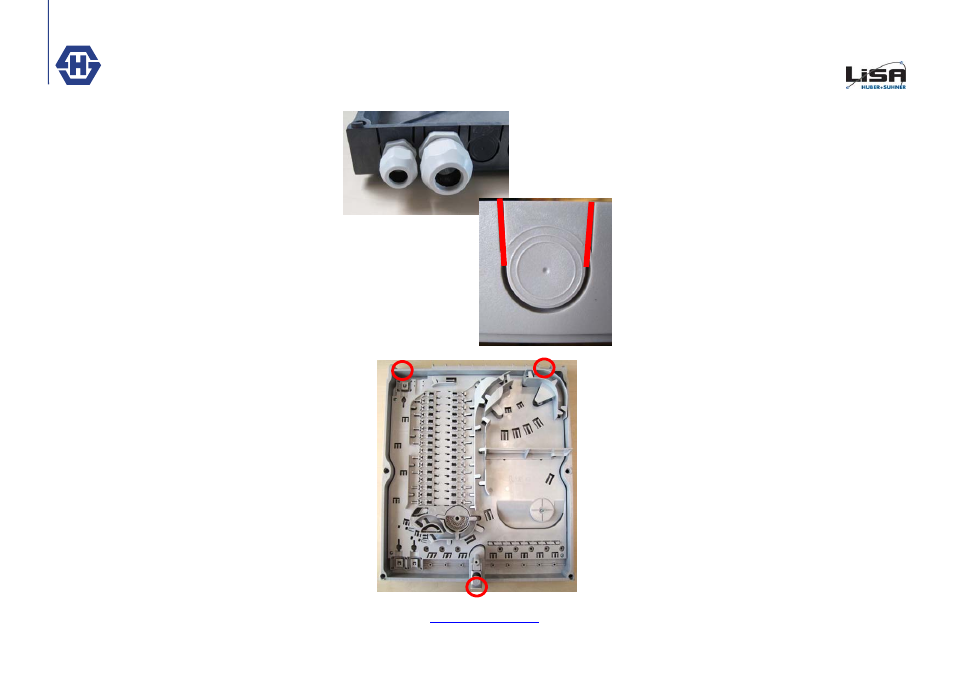
III. Preparing Cable entries (U-Shape and
Cable Glands)
At the bottom side of the box you can open 10 holes
for Cable entry or exit with U-Shapes or Cable Glands
(Pos. 1-8, A, B, C, D). If you are using Cable Glands
you have to drill the right hole. You can only use M16
Cable Glands with a small form, if you need to use
M25 Cable Glands you can only use every second po-
sition.
If you are using U-Shapes, you have to make a cut
according to the red line on the picture. After that you
can break out the rest of the material easily.
III. Kabeleinführung vorbereiten
(Kabelverschraubung und U-Shapes)
An der Unter- und Oberseite der Base können 10 Öff-
nungen für Ein- oder Austretende Kabel mittels U-
Shape oder Kabelverschraubung gemacht werden
(Pos. 1-8, A, B, C, D). Für Kabelverschraubungen
muss mit einem Stufenbohrer ein passendes Loch ge-
bohrt werden. Eine Zentrierhilfe ist in der Mitte der Ein-
führungsposition vorhanden. Es können nur Kabelver-
schraubungen (M16) eingebaut werden die eine
schmale Form haben. Bei Verwendung von M25 Ver-
schraubungen kann nur jede zweite Öffnung benutzt
werden.
Werden U-Shapes benutzt, muss entsprechend dem
roten Strich auf dem Foto gesägt werden. Der Rest
des U-Shapes lässt sich danach sehr einfach ausbre-
chen.
IV. Wandmontage Box
Zur Wandmontage der Box muss die Base an die
vorgesehene Wand gehalten werden. Anschliessend
müssen die drei Befestigungsloch Positionen auf der
Wand markiert werden. Danach können die Löcher
gebohrt und die Base an der Wand befestigt werden.
IV. Wallmounting Box
For Wallmounting, put the Box on the wall, adapt the
three fixing hole point to the wall. After that you can
drill the holes and fix the box on the wall.