Mfr 4, mfr 5, Timers, Technical data – CONTA-CLIP MFR Multi-functional timing Benutzerhandbuch
Seite 2: Functions, Connections
Subject to alterations and errors
Release 04/11
Timers
Timers multifunctional
Up to 7 functions
7 time ranges
Wide input voltage range
1 change over contact
Width 17.5 mm
Installation design
Technical data
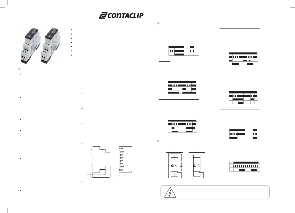
1. Functions
The function has to be set before connecting the relay to the supply
voltage.
E
ON delay
R
OFF delay
Ws
Single shot leading edge with control input
Wa
Single shot trailing edge with control input
Es
ON delay with control input
Wu
Single shot leading edge voltage controlled
Bp
Flasher pause first
2. Time ranges
Time range
Adjustment range
1s
50ms
1s
10s
500ms
10s
1min
3s
1min
10min
30s
10min
1h
3min
1h
10h
30min
10h
100h
5h
100h
3. Indicators
Green LED U/t ON:
indication of supply voltage
Green LED U/t flashes: indication of time period
Yellow LED R ON/OFF: indication of relay output
4. Mechanical design
Self-extinguishing plastic housing, IP rating IP40
Mounted on DIN-rail TS 35 according to EN 60715
Mounting position:
any
Shockproof terminal connection according to VBG 4 (PZ1 required),
IP rating IP20
Tightening torque:
max. 1Nm
Terminal capacity:
1 x 0.5 to 2.5mm² with/without multicore cable end
1 x 4mm² without multicore cable end
2 x 0.5 to 1.5mm² with/without multicore cable end
2 x 2.5mm² flexible without multicore cable end
5. Input circuit
Supply voltage:
Terminals A1(+)-A2
MFR 4 24-240VAC/DC: 24 to 240V AC/DC
Tolerance:
-15% to+10%
MFR 5 12-240VAC/DC: 12 to 240V AC/DC
Tolerance:
-10% to+10%
Rated consumption:
4VA (1.5W)
Rated frequency:
AC 48 to 63Hz
Duty cycle:
100%
Reset time:
100ms
Residual ripple for DC: 10%
Drop-out voltage:
>30% of minimum rated supply voltage
Overvoltage category:
III (in accordance with IEC 60664-1)
Rated surge voltage:
4kV
6. Output circuit
1 potential free change over contact
Rated voltage:
250V AC
Switching capacity:
2000VA (8A / 250V)
Fusing:
8A fast acting
Mechanical life:
20 x 10
6
operations
Electrical life:
2 x 10
5
operations
at 1000VA resistive load
Switching frequency:
max. 6/min at 1000VA resistive load
(in accordance with IEC 60947-5-1)
Overvoltage category:
III (in accordance with IEC 60664-1)
Rated surge voltage:
4kV
7. Control input
Input not potential free:
Terminals A1-B1
Loadable:
yes
Max. line length:
10m
Trigger level (sensitivity):
automatic adaption to supply voltage
Min. control pulse length:
DC 50 ms / AC 100 ms
8. Accuracy
Base accuracy:
±1% of maximum scale value
Adjustment accuracy:
<5% of maximum scale value
Repetition accuracy:
<0.5% or ±5ms
Voltage influence:
-
Temperature influence:
≤0.01% / °C
9. Ambient conditions
Ambient temperature:
-25 to +55°C
Storage temperature:
-25 to +70°C
Transport temperature:
-25 to +70°C
Relative humidity:
15% to 85%
(in accordance with IEC 60721-3-3
class 3K3)
Pollution degree:
2 (in accordance with IEC 60664-1)
10. Dimensions
11. Weight
Single packing:
72g
Package 10pcs:
670g per Package
MFR 4, MFR 5
Subject to alterations and errors
Functions
ON delay (E)
When the supply voltage U is applied, the set interval t begins (green
LED U/t flashes). After the interval t has expired (green LED U/t
illuminated) the output relay R switches into on-position (yellow LED
illuminated). This status remains until the supply voltage is interrupted.
If the supply voltage is interrupted before the expiry of the interval t,
the interval already expired is erased and is restarted when the supply
voltage is next applied.
OFF delay (R)
The supply voltage U must be constantly applied to the device (green
LED U/t illuminated). When the control contact S is closed, the output
relay R switches into on-position (yellow LED illuminated). If the control
contact is opened, the set interval t begins (green LED flashes). After
the interval t has expired (green LED U/t illuminated) the output relay
switches into off-position (yellow LED not illuminated). If the control
contact is closed again before the interval t has expired, the interval
already expired is erased and is restarted.
Single shot leading edge with control input (Ws)
The supply voltage U must be constantly applied to the device (green
LED U/t illuminated). When the control contact S is closed, the output
relay R switches into on-position (green LED U/t illuminated) and the
set interval t begins (green LED U/t flashes). After the interval t has
expired (green LED U/t illuminated) the output relay switches into
off-position (yellow LED not illuminated). During the interval, the control
contact can be operated any number of times. A further cycle can only
be started when the cycle run has been completed.
Single shot trailling edge with control input (Wa)
The supply voltage U must be constantly applied to the device (green
LED U/t illuminated).
Closing the control contact S has no influence on the condition of the
output R. When the control contact is opened, the output relay switches
into on-position (yellow LED illuminated) and the set interval t begins
(green LED U/t flashes). After the interval t has expired (green LED U/t
illuminated), the ouput relay switches into off-position (yellow LED not
illuminated). During the interval, the control contact can be operated
any number of times. A further cycle can only be started when the cycle
run has been completed.
ON delay with control input (Es)
The supply voltage U must be constantly applied to the device (green
LED U/t illuminated).
When the control contact S is closed, the set interval t begins (green
LED U/t flashes). After the interval t has expired (green LED U/t
illuminated) the output relay R switches into on-position (yellow LED
illuminated). This status remains until the control contact is opened
again.
If the control contact is opened before the interval t has expired , the
interval already expired is erased and is restarted with the next cycle.
Single shot leading edge voltage controlled (Wu)
When the supply voltage U is applied, the output relay R switches
into on-position (yellow LED illuminated) and the set interval t begins
(green LED U/t flashes). After the interval t has expired (green LED U/t
illuminated) the output relay switches into off-position (yellow LED not
illuminated). This status remains until the supply voltage is interrupted.
If the supply voltage is interrupted before the interval t has expired, the
output relay switches into off-position. The interval already is erased
and is restarted when the supply voltage is next applied.
Flasher pause first (Bp)
When the supply voltage U is applied, the set interval t begins (green
LED U/t flashes). After the interval t has expired, the output relay R
switches into on-position (yellow LED illuminated) and the set interval t
begins again. After the interval t has expired, the output relay switches
into off-position (yellow LED not illuminated).
The output relay is triggered at a ratio of 1:1 until the supply voltage is
interrupted.
MFR 4, MFR 5
17,5mm
60mm
87
m
m
44mm
5mm
45
m
m
with control input
without control input
U
U/t
R
LED
<t
t
U
U/t
S
R
LED
<t
t
<t
U
U/t
S
R
LED
t
t
A1 B1
15
A2
16
18
A1
R
15
16 18
U ~
(+)
(-)
A2
S
A1 B1
15
A2
16
18
A1
R
15
16 18
U ~
(+)
(-)
A2
U
U/t
S
R
LED
t
t
U
U/t
S
R
LED
t1
<t
U
U/t
R
LED
<t
t
U
U/t
R
LED
t
t
t
t
Connections
Danger!
Never carry out work on live parts! Danger of fatal injury! The product must not be
used in case of an obvious damage. To be installed by an authorized person.