BECKHOFF BK8000 Benutzerhandbuch
Seite 21
RS485-Koppler BK8000
BK8000
21
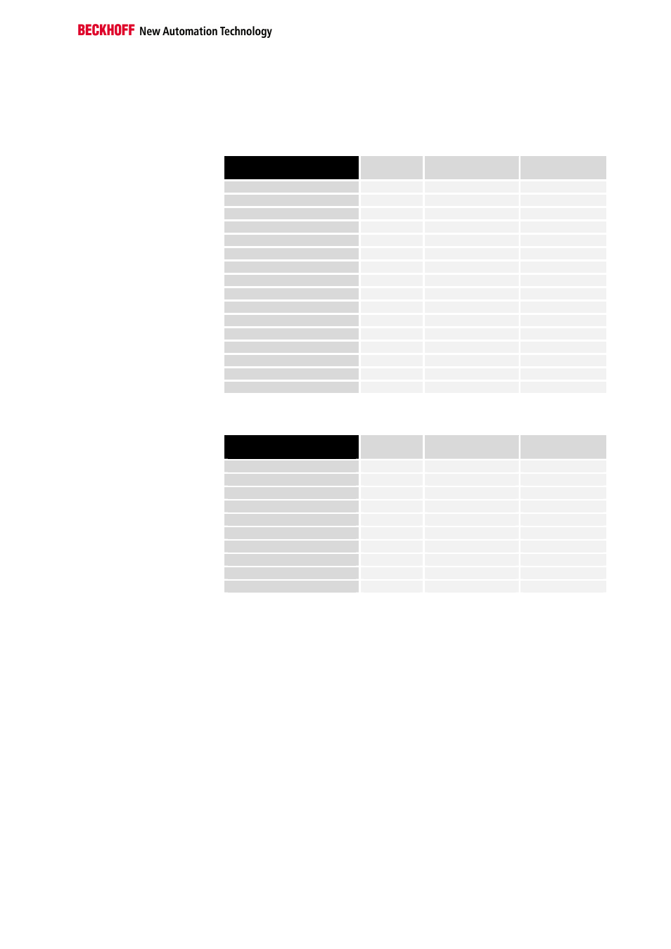
Das Prozeßabbild auf dem Buskoppler setzt sich somit folgendermaßen
zusammen:
Prozeßabbild der Eingänge:
relative Byteadresse
im PAE des Buskoppler
Bitposition Position im Block Busklemme
0, 1
keine
POS06
KL3002, Kanal 1
2, 3
keine
POS06
KL3002, Kanal 2
4
0
POS01
KL1002, Kanal 1
4
1
POS01
KL1002, Kanal 2
4
2
POS02
KL1002, Kanal 1
4
3
POS02
KL1002, Kanal 2
4
4
POS03
KL1002, Kanal 1
4
5
POS03
KL1002, Kanal 2
4
6
POS04
KL1114, Kanal 1
4
7
POS04
KL1114, Kanal 2
5
0
POS04
KL1114, Kanal 3
5
1
POS04
KL1114, Kanal 4
5
2
POS05
KL1114, Kanal 1
5
3
POS05
KL1114, Kanal 2
5
4
POS05
KL1114, Kanal 3
5
5
POS05
KL1114, Kanal 4
Prozeßabbild der Ausgänge:
relative Byteadresse
im PAA des Buskoppler
Bitposition Position im Block Busklemme
0, 1
keine
POS12
KL4002, Kanal 1
2, 3
keine
POS12
KL4002, Kanal 2
4
0
POS08
KL2012, Kanal 1
4
1
POS08
KL2012, Kanal 2
4
2
POS09
KL2012, Kanal 1
4
3
POS09
KL2012, Kanal 2
4
4
POS10
KL2012, Kanal 1
4
5
POS10
KL2012, Kanal 2
4
6
POS11
KL2012, Kanal 1
4
7
POS11
KL2012, Kanal 2
Request
In dem Request (Ausgangsdaten an den Koppler) vom Master an den Sla-
ve (BK8000) müssen folgende Daten übertragen werden:
1. Byte:
0x50 (´P´)
Startkennung
2. Byte:
0x03
3 Ausgangsdatenworte (5 Byte)
3. Byte:
0x12
beliebig wählbare Message Ident
4. Byte:
0x05
eingestellte Buskoppler Adresse
5. Byte:
0xXX
Daten-Byte 0
6. Byte:
0xXX
Daten-Byte 1
.
.
.
9. Byte:
0xXX
Daten-Byte 4
10. Byte:
0xXX
Dummy-Byte
11. Byte:
0x??
Aus den Bytes (1-10) errechnete Prüf-
summe
Response
Der Buskoppler sendet daraufhin die folgende Response (Eingangsdaten
des Buskopplers):
1. Byte:
0x70 (´p´)
Startkennung
2. Byte:
0x05
3 Eingangsdatenworte (6 Byte)
4. Byte:
0x12
Rücksendung der Message Ident