Connections on the p8 rear panel, Control elements on the m8 front panel, Risk of electric shock – Quadral AURUM M8 Benutzerhandbuch
Seite 10
Using the menu item (HP), the headphone output on the back of the device (rear
panel) is activated or deactivated.
If the headphone output is activated, the signal path to the pre-amplifier outputs
is interrupted!
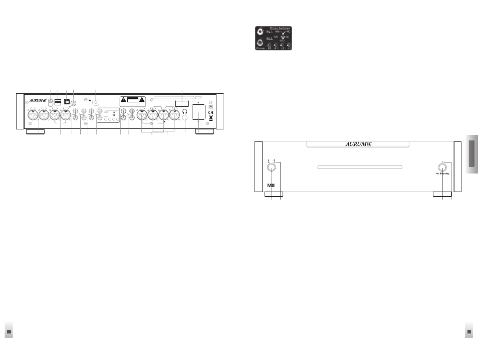
Connections on the P8 rear panel
1 XLR 2
Balanced Inputs
2 XLR 1
Balanced Inputs
3 AUX
Analogue inputs for audio signals
4 Tuner
Analogue inputs for your radio
5 CD
Analogue inputs for CD players
6 Phono
Input (MM + MC)
7 Direct Bypass These inputs bypass the audio and volume settings and are
intended for use as part of home cinema installations
8 OUT 3
Unbalanced Outputs
9 OUT 2
Balanced Outputs
10 OUT 1
Balanced Outputs
11 Headphone output Stereo jack socket
12 Power supply socket
13 Power switch Completely disconnects the device from the power supply
14 Ground
Phono ground connection
15 SPDIF
Co-axial digital input
16 TosLink
Optical digital input
Note: PHONO
In order to handle the signal paths for Phono MM (Moving
Magnet) and MC (Moving Coil) as optimally as possible, the
changing between the operating modes is done on the back
side of the devices and individually per channel!
The L1 and R1 switches allow the selection between the MM (switch to the left) and
MC operation. (switch to the right)
The multi-stage switches L2 and R2 offer the option to adjust the impedance for
different MC systems when in the MC operating mode. (Left = 120 Ohm, Centre = 600
Ohm and Right = 40 Ohm)
Control elements on the M8 front panel
1 Speakers: Button for speaker switching
Sequence: Group A / B / A+B / OFF
2 LED: Loudspeaker group display
3 Operating Display: This display will light up blue, when the device is turned on and
in operation
4 On/Off Button: Press this button to turn the M8 on. Press this button again to switch
the device off (standby). During standby operation, all of the settings remain
saved.
5 Standby Display: This display is blue whenever the unit is in standby mode and
this indicates that the unit can be switched on again at any time using either the
remote control or button (4)
Fuse:
100V/115V: T250 mA L250V
230V: T125 mA L250V
~50/60 Hz
max. Power Cons.: 10W
quadral GmbH & Co. KG - Am Herrenhäuser Bahnhof 26-28 - D-30419 Hannover
On
Off
Out 2
L
R
Out 1
L
R
Out 3
R
L
R
L
R
L
R
L
Aux
Tuner
CD
Phono
L2
L1
R2
R1
Direct
Bypass
40
600
120
R/L 2
MC
MM
R/L 1
Phono Switches
XLR 2
L
R
XLR 1
L
R
Phono
GND
USB
TosLink
SPDIf
Digital In
Link
Out
Handmade in Germany
W A R N I N G :
TO REDUCE THE RISK
OF ELECTRICAL SHOCK
OR FIRE, DO NOT EXPOSE
THIS
APPLIANCE
TO
MOISTURE
OR
RAIN.
DO NOT REMOVE COVER. NO USER
SERVICEABLE PARTS INSIDE. REFER
SERVICING TO QUALIFIED PERSONNEL.
CAUTION
RISK OF ELECTRIC SHOCK
DO NOT OPEN
1
2
3 4 5 6
7 8
9
10
11
12
13
14
15
16
17
18
1
4
3
2
5