Installation, Video input, Alarm input/output – Eneo DLR-2104/3.0TBV Benutzerhandbuch
Seite 37
7
Installation
No special tools are required to install the DVR. Refer to the installation manuals for the other items that make
up part of your system.
Your DVR can be used with either NTSC or PAL equipment.
NOTE: You cannot mix NTSC and PAL equipment. For example you cannot use a PAL camera and an
NTSC monitor.
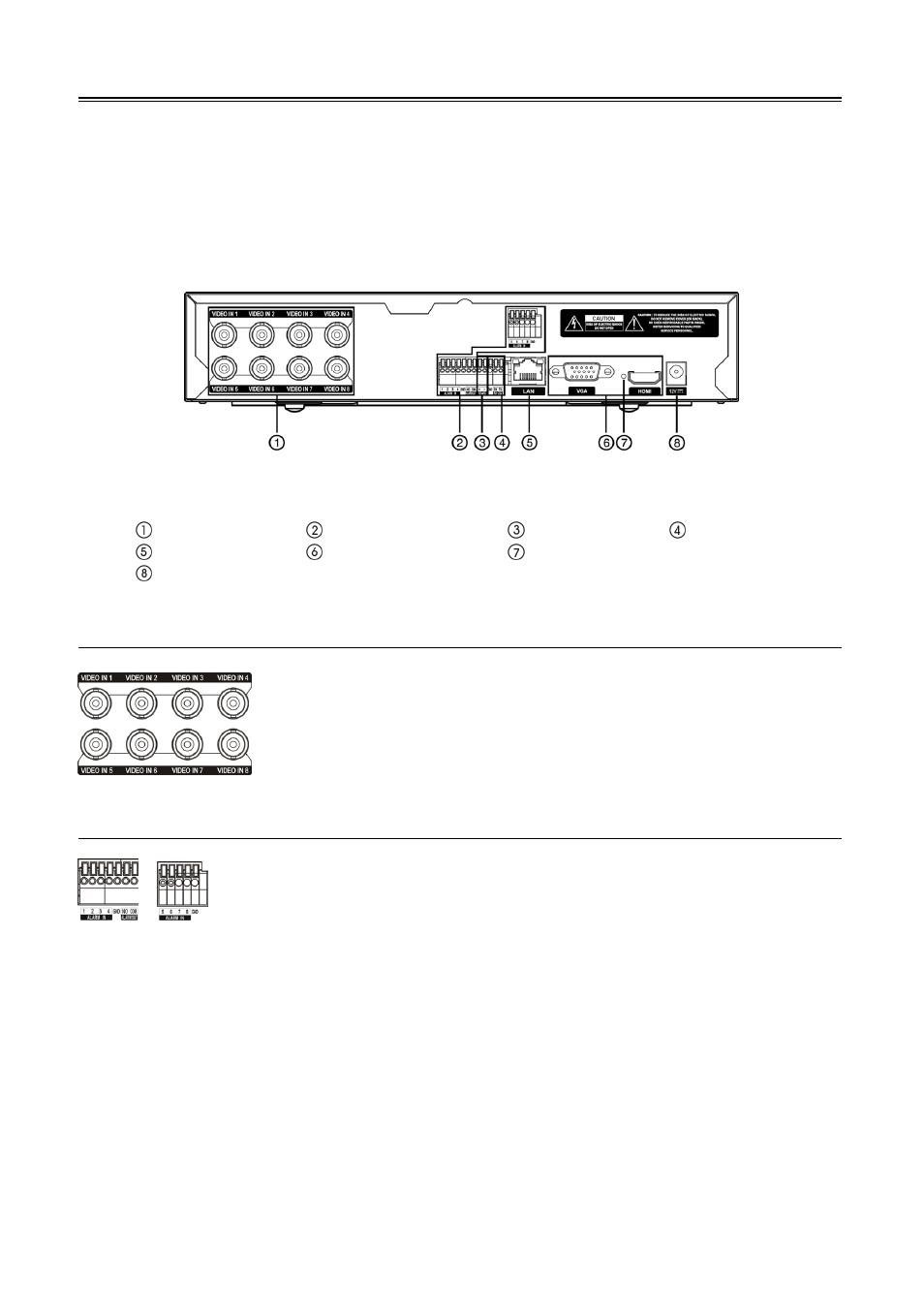
< 8-Channel DVR rear panel >
Video Input
Alarm Input/Output
RS485 Port
RS232 Port
Network Port
Video Out
Factory Reset Switch
Power Cord Connector
Video Input
Alarm Input/Output
Alarm In 1 to 8: You can use external devices to signal the DVR to react to events. Mechanical or electrical
switches can be wired to the Alarm In and GND (Ground) connectors. The threshold voltage of electrical switches
for NC (Normally Closed) is above 2.4V and for NO (Normally Open) is below 0.3V, and should be stable at
least 0.5 seconds to be detected. The voltage range of alarm input is from 0V to 5V.
GND (Ground): Connect the ground side of the Alarm input and/or alarm output to the GND connector.
NOTE: All the connectors marked GND are common.
NO (Normally Open): Connect the device to the COM and NO (Normally Open) connector. NO is a relay
output which sinks 1A@30VDC.
Connect the coaxial cables from the video sources to the BNC Video In connectors.
NOTE: To make connections on the Alarm Connector Strip, press and hold the
button and insert the wire in the hole below the button. After releasing the button,
tug gently on the wire to make certain it is connected. To disconnect a wire, press
and hold the button above the wire and pull out the wire.