Multi-Contact MA030 Benutzerhandbuch
Seite 4
Advanced Contact Technology
4 / 8
www.multi-contact.com
6
Tab. 1
L
2
A
7
}
8
Typ
Type
Crimpzange
Crimping pliers
Bestell-Nr.
Order No.
Leiterquerschnitt
Conductor cross-section
Crimpeinsatz
Crimp insert
Bestell-Nr.
Order No.
Crimpstellen
Anzahl
Number of
crimping
Prüfmass
Control
dimension
FSA20.../P50
M-PZ-T2600
18.3710
50mm
2
TB11-14.5
18.3713
1
11,4
FSA20.../P70
M-PZ-T2600
18.3710
70mm
2
TB8-17
18.3711
2
13,4
FSA20.../P95
M-PZ-T2600
18.3710
95mm
2
TB20
18.3714
2
16,4
FSA20.../P120
V1311C
1)
120mm
2
B22
2)
1)
1
16,3
FSA20.../P150
V1311C
1)
150mm
2
B25
2)
1)
1
20,3
FSA20.../P185
V1311C
1)
185mm
2
13CB27
1)
2
20,5
FSA20.../P50H
M-PZ-T2600
18.3710
50mm
2
TB12-14
1)
1
11,6
FSA20.../P70H
M-PZ-T2600
18.3710
70mm
2
TB10-16
1)
2
13,2
FSA20.../P95H
M-PZ-T2600
18.3710
95mm
2
TB8-18
1)
2
14,0
FSA20.../P120H M-PZ-T2600
18.3710
120mm
2
B7-19
1)
2
15,4
FSA20.../P150H V1311C
1)
150mm
2
B22
2)
1)
1
16,3
FSA20.../P185H V1311C
1)
185mm
2
13CB24
1)
2
17,7
1) Nicht von MC geliefert.
2) Backenhalter V1330 nötig
1) Not delivered by MC.
2) Insert holder V1330 is required
Leitungskonfektionierung
Wire assembly
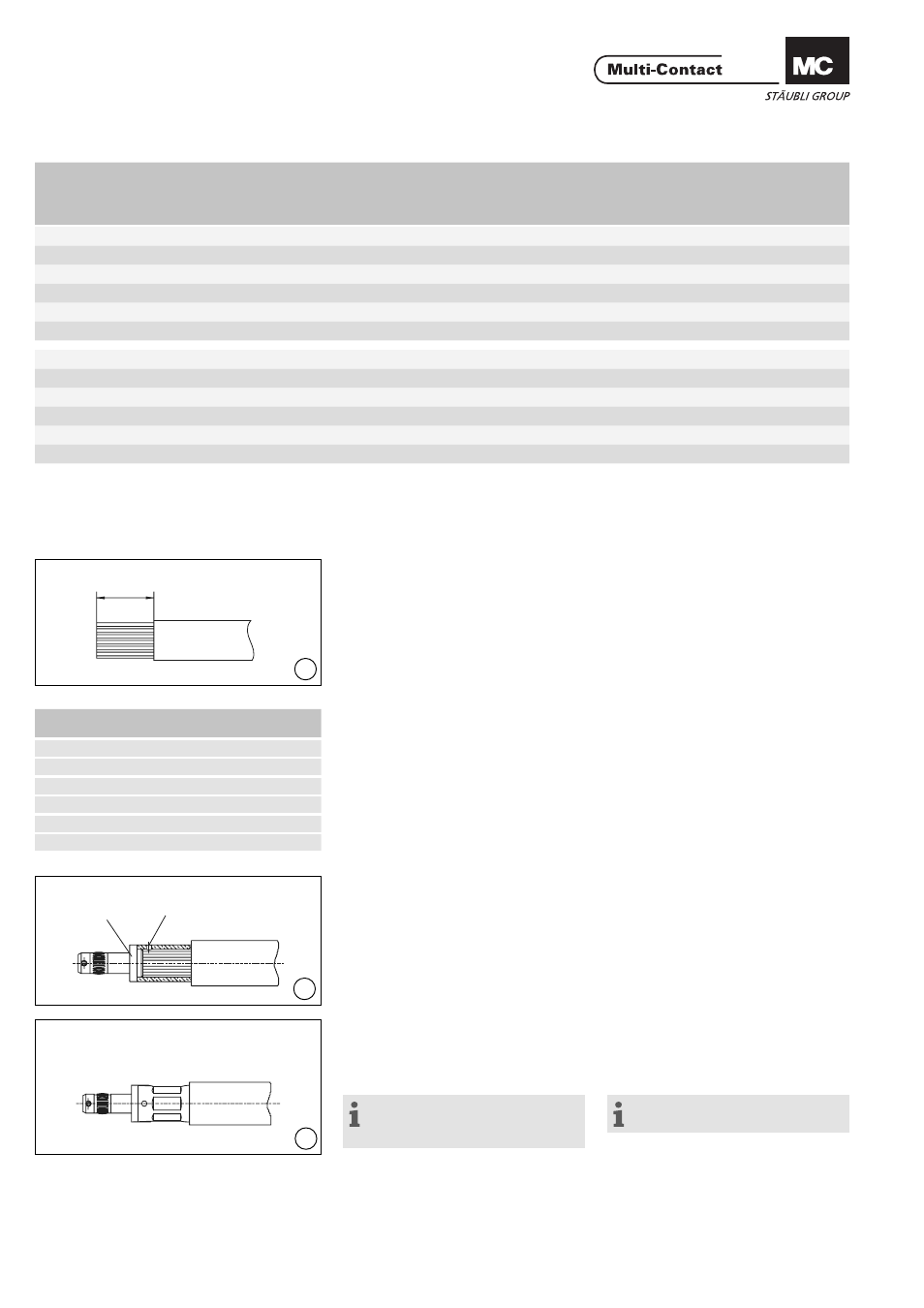
(ill. 6)
Leitung auf Länge L abisolieren. Siehe
Tab. 2.
(ill. 6)
Strip the cable to the length L. See
Tab. 2.
(ill. 7)
Leitung mit allen Einzeldrähten in die
Crimphülse (2) einführen. Die Leitung
muss im Sichtloch A sichtbar sein.
(ill. 7)
Insert the cable with all strands into
the crimping sleeve (2). Cable must be
visible in the sight hole A.
(ill. 8)
Crimphülse vercrimpen mit Crimp-
zange Elpress und dem entsprechen-
den Einsatz (siehe Tab. 1, Seite 4/8).
Crimpzone beachten!
Hinweis:
Leitung nicht anschweissen oder
anlöten!
(ill. 8)
Crimp the cable with the crimping pli-
ers and the correct insert (see Tab. 1,
page 4/8). Be sure to crimp within the
crimping zone.
Note:
Do not solder or weld the cable!
Tab. 2
Leiterquerschnitt
Conductor cross section
Länge L (mm)
Length L (mm)
50mm
2
27
70mm
2
27
95mm
2
29
120mm
2
30
150mm
2
33
185mm
2
38