Multi-Contact MA089 Benutzerhandbuch
Seite 3
Advanced Contact Technology
www.multi-contact.com
3 / 4
1
12
68
Tief
e 8 mm maxi
Depth
8 mm
maxi
Technische Eigenschaften
Technical characteristics
- Max. Bemessungsstrom ���������������������������������������������������� 100 A
- lcc / 1 s �������������������������������������������������������������������������������� 1,4 kA
- lcc / 2 s ������������������������������������������������������������������������������ 0,94 kA
- lpeak ���������������������������������������������������������������������������������� 4,7 kA
- Zulässige Belastung pro Scharnier ������������������������������������250 kg
- Schutzart, gesteckt �������������������������������������������������������������� IP66
- Salznebelsprühtest ��������������������������������������������������������������500 h
- Entsprechender Kabelquerschnitt ����������������������������������� 16 mm
2
- Öffnungs-/Schliesszyklen ��������������������������������������� 15000 Zyklen
- Türmontage/-demontage �������������������������������������������� 500 Zyklen
- Ein- oder Ausschubkraft ���������������������������������������������������� ~ 25 N
- Max. rated current ����������������������������������������������������������� 100 A
- Icc/1s ������������������������������������������������������������������������������ 1.4 kA
- lcc / 2 s ��������������������������������������������������������������������������� 0,94 kA
- Ipeak ������������������������������������������������������������������������������� 4.7 kA
- Allowable charge per hinge ������������������������������������������� 250 Kg
- Degree of protection, mated ��������������������������������������������� IP66
- Salt mist spray test �����������������������������������������������������������500 h
- Equivalent cable cross section ������������������������������������� 16 mm
2
- Open/Close cycles ������������������������������������������������15000 cycles
- Door mounting/unmounting ������������������������������������500 cycles
- Insertion or extraction force ������������������������������������������� ~ 25 N
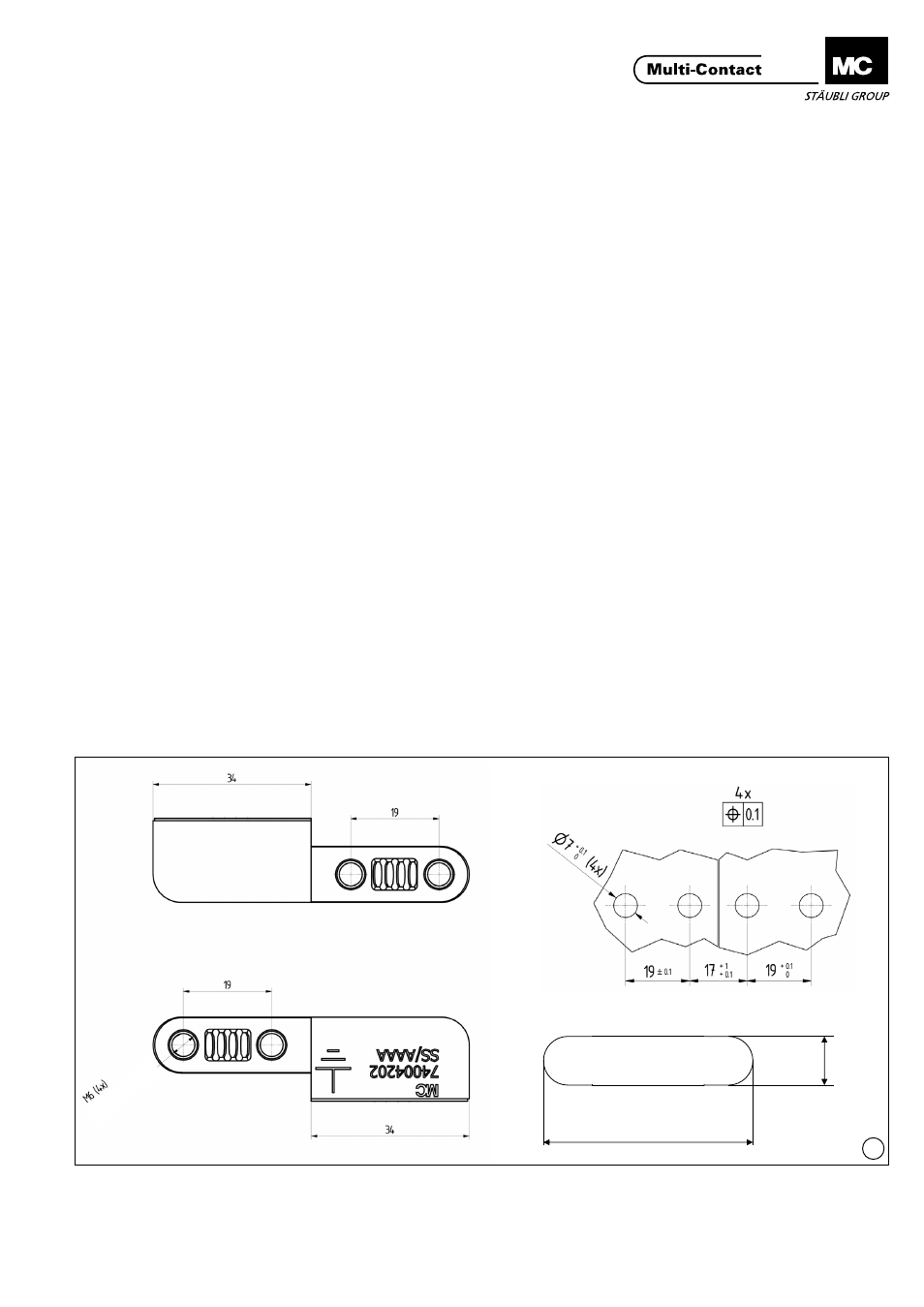
Bohrplan und Befestigungsbereiche
Drilling plan and fixing areas
Es müssen Befestigungslöcher mit Ø 7 mm
+0,1
gebohrt werden
( Stanzen ist nicht erlaubt ). Gemäss nachfolgendem Bohrplan.
Art der Befestigungsplatte
Die Stärke der Metallplatte muss ≥ 0,7 mm betragen.
Die Montagefläche muss aus:
- Edelstahl für 19.0303 sein
- Aluminiumlegierung für 19.0304 sein
- Andere Materialoberfläche: auf Anfrage
Bei einer Stahloberfläche darf auf einer Fläche in der Grösse der
Auflagefläche keine Farbe angebracht werden (siehe ill. 1).
Befestigungsbereich
Folgendes ist zu beachten :
– Der Befestigungsbereich muss ≤ 40 μm flach sein.
– Die Oberfläche muss eine Rauheit von ≤ 10 μm aufweisen.
– Feinbearbeitungen wie Farb- oder Epoxidharzanstriche sind zu
vermeiden.
It is necessary to drill fixing holes Ø 7 mm
+0�1
(punching is not
permitted)� According to the below drilling plan�
Type of fixing panel
The thickness of the metal panel must be ≥ 0.7 mm.
The mounting surface must be :
- stainless steel for part 19.0303
- aluminium alloy for part 19.0304
- Other cabinet material: on request
On a steel surface, the paint must be omitted on an area of the
same dimensions as the contact surface (see ill� 1)�
Fixing area
It is essential to note the following:
- The flatness of the fixing area must be ≤ 40 μm
- The roughness of the surface must be ≤ 10 μm
- Any finishing like painting or epoxy powder must be avoided.
Auflagefläche
Contact surface