Technical manual – Merit Medical Worley Advanced CSG Coronary Sinus Guide Benutzerhandbuch
Seite 3
Technical Manual
en Hemostatic Tear-away Introducer System
with Infusion Side Port
da Haemostatisk skræl-væk indførings system med
infusions sideport
de Hämostatisches Abreiβ-Einführsystem mit
Infusionseitenport
el Σύστημα Αιμοστατικής Αποκόλλησης Εισαγωγέα με
‘Έγχυση Πλευρικής Θύρας
es Sistema introductor hemostático desechable con
puerto lateral para infusión
fi Infuusiosivuportilla varustettu hemostaattinen
irtirevittävä sisäänvientijärjestelmä
fr Système d’introduction hémostatique à détacher
avec orifice latéral de perfusion
it Sistema introduttore asportabile emostatico con
porta di infusione laterale
ja
引き剥がし型止血用導入器装置
(注入サイドポート付き)
nl Hemostatisch verwijderbaar inbrengsysteem met
zijopening voor infusie
no Hemostatisk avtakbar introduksjonssystem med
infusjonssideport
pt Sistema introdutor hemostático com orifício lateral
de infusão, que se retira rasgando
sv Hemostatiskt avdragbart introducersystem med
infusionssidoport
en Directions for Use
3
da Brugsvejledning
4
de Gebrauchsanweisung
5
el
Οδηγίες χρήσης
6
es
Instrucciones de uso
7
fi
Käyttöohje
8
fr
Mode d’emploi
9
it
Istruzioni per l’uso
10
ja
使用上の注意
12
nl
Gebruiksaanwijzing
13
no Bruksanvisning
14
pt
Instruções de Utilização
15
sv
Bruksanvisning
16
For U.S.-California Only.
Proposition 65, a State of California voter initiative,
requires the following notice:
WARNING: This product and its packaging have been ster-
ilized with ethylene oxide. This packaging may expose you to
ethylene oxide, a chemical known to the state of California
to cause cancer or birth defects or other reproductive harm.
CAUTION: Federal (U.S.A.) Law restricts this device to sale by
or on the order of a physician.
The hemostatic splittable sheath is protected by Patent In-
surance. USA Patent 7,462,184. European Patent EP1360972.
Other USA and Worldwide Patents pending.
en-Directions for Use
This device is intended for one time use only. Read
instructions prior to use.
Indications
For the introduction of various types of pacing or
defibrillator leads and catheters.
Contraindications
Use of the Coronary Sinus Guide / Lateral Vein Introducer
(CSG/LVI) systems is contraindicated for the following:
• Patients with an existing or possible occlusion of the
coronary vessels or unsuitable anatomy of the coronary
veins
• Patients with active systemic infection
Possible Negative Side Effects / Adverse Events
Coronary Sinus Guide / Lateral Vein Introducer (CSG. LVI)
systems should be used by physicians familiar with
percutaneous catheter introduction. Complications which
may be associated with the use of catheter introducer
systems include, but are not limited to, the following:
• Air embolism
• Allergic reaction to contrast media
• Arterial wall damage
• Bleeding
• Cardiac arrhythmias
• Cardiac tamponade
• Chronic nerve damage
• Damage to the heart valves
• Hematoma at the puncture site
• Infection
• Local tissue response, fibrotic tissue formation
• Myocardial damage
• Myocardial infarction
• Plaque dislodgement
• Pneumothorax
• Stroke and death
• Thrombus formation/emboli
• Vascular occlusion
• Vascular spasm
• Venous or cardiac perforation
Warnings
• This product is sensitive to light. Do not use if stored
outside the protective outer carton. Store in a cool, dark,
and dry place.
• Infusion through the side port can be done only after all
air is removed from the unit. Improper use of the
transvalvular insertion tool (TVI) can cause air embolism
and back bleeding.
• Do not use this device in patients who cannot be
appropriately anticoagulated. When tested in non-
anticoagulated sheep, this device has shown thrombus
formation, however, heparinized studies alleviated
the concern.
Precautions
• Do not alter this device in any way.
• Single Use Devices: This single-use product is not
designed or validated to be reused. Reuse may cause a
risk of cross-contamination, affect the measurement
accuracy, system performance, or cause a malfunction
as a result of the product being physically damaged
due to cleaning, disinfection, re-sterilization, or reuse.
• Federal law (U.S.A.) restricts this device to sale by or
on the order of a physician.
• Aspiration and saline flushing of the sheath, dilator,
and valve should be performed to help minimize the
potential for air embolism and clot formation.
• Indwelling introducer sheaths should be internally
supported by a catheter, pacing lead, or dilator.
• Dilators, catheters, and pacing leads should be removed
slowly from the sheath. Rapid removal may damage the
valve members resulting in blood flow though the valve.
Never advance or withdraw guide wire or sheath when
resistance is met. Determine cause by fluoroscopy and
take remedial action.
• When injecting or aspirating through the sheath, use
the side port only.
• When using the transvalvular insertion tool (TVI),
lead size may not exceed 6.2F.
• When using the TVI always keep the exposed
proximal end covered to prevent air embolization
and back bleeding.
Use Sterile Technique A suggested procedure:
1. Peel open package and place contents on sterile field.
2. Prep skin and drape in area of anticipated venipuncture
as desired.
3. Distend the subclavian vein. The subclavian vein is difficult
to locate unless it is distended by raising the patient’s legs
to a 45 degree angle or by using the Trendelenburg position.
The vein will be much easier to locate if the patient is well
hydrated.
4. Insert needle into vessel. The needle position should
be verified by observing venous blood return.
5. The angle of the needle should be adjusted depending
on the patient’s build: shallow in a thin person, deeper in a
heavy-set person. Use an 18g needle, 7cm (2-3/4 in.) long.
6. Aspirate the puncture needle using the 12cc syringe.
7. Remove the syringe and insert soft tip of guide wire
through the introducer needle into the vessel. Advance
guide wire guide to required depth. Leave an appropriate
amount of guide wire exposed. At no time should the guide
wire be advanced or withdrawn when resistance is met.
Determine the cause of resistance before proceeding. Fluoro-
scopic verification of the guide wire’s entrance into the
superior vena cava and right atrium is suggested.
8. Hold guide wire in place and remove introducer
needle. Do not withdraw the guide wire back into
the cannula as this may result in separation of the
guide wire. The cannula should be removed first.
9. Insert the straight vessel dilator into the sheath until
the dilator cap folds over the valve housing and
secures the dilator onto sheath assembly.
10. Thread the dilator/sheath assembly over the guide wire.
11. Advance the dilator and sheath together with a twisting
motion over the guide wire and into the vessel. Fluoroscopic
observation is advisable. Attaching a clamp or hemostat to
the proximal end of the guide wire will prevent inadvertent-
ly advancing the guide wire entirely into the patient.
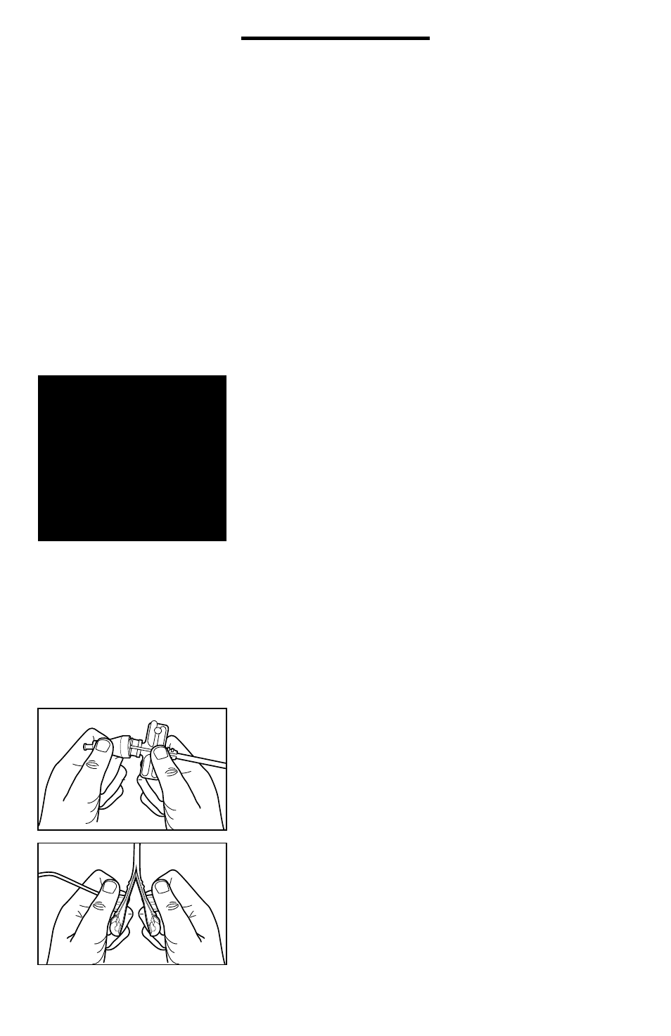
12. Once assembly is fully introduced into the venous
system, separate the dilator cap from the sheath valve
housing by rocking the dilator cap off the hub.
(see Figure 1)
13. Slowly retract the dilator, leaving the sheath and wire in
position. The hemostasis valve will reduce the loss of blood
and the inadvertent aspiration of air through the sheath.
14. Remove the curved braided core from the package and
thread the exposed proximal portion of the retained
guide wire into the distal end of the braided core.
15. Feed the guide wire through the curved braided core or
braided sheath until the proximal end of the guide wire can
be secured with either a clamp or hemostat before advanc-
ing the curved dilator into the indwelling sheath.
16. Do not advance the braided core into the sheath until
the guide wire has been completely passed through the core
and the wire is secured with a hemostat or clamp in order
to prevent inadvertently advancing the guide wire entirely
into the patient.
17. Advance the braided core into the sheath and observe
fluoroscopically as the wire and distal end of the core extend
past the distal end of the sheath and are positioned in the
right atrium.
18. Manipulate the distal end of the guide wire or sheath
into the desired location (coronary sinus etc.) by combining
a twisting motion of the guide wire or sheath with the
gentle probing of the guide wire or sheath itself. Fluoroscopy
in the left anterior oblique (LAO) position is helpful. Advance
the CSG sheath into the mid coronary sinus and establish its
position by injecting contrast material through the side port.
19. Once the guide wire is in the desired location advance
the sheath over the wire until the tip rests in the desired
location. It is advisable to leave a short segment of wire
extending past the distal end of the tip to minimize any
3