Multi-Contact MA011 Benutzerhandbuch
Seite 3
Advanced Contact Technology
www.multi-contact.com
3 / 4
1
Tab. 1
2
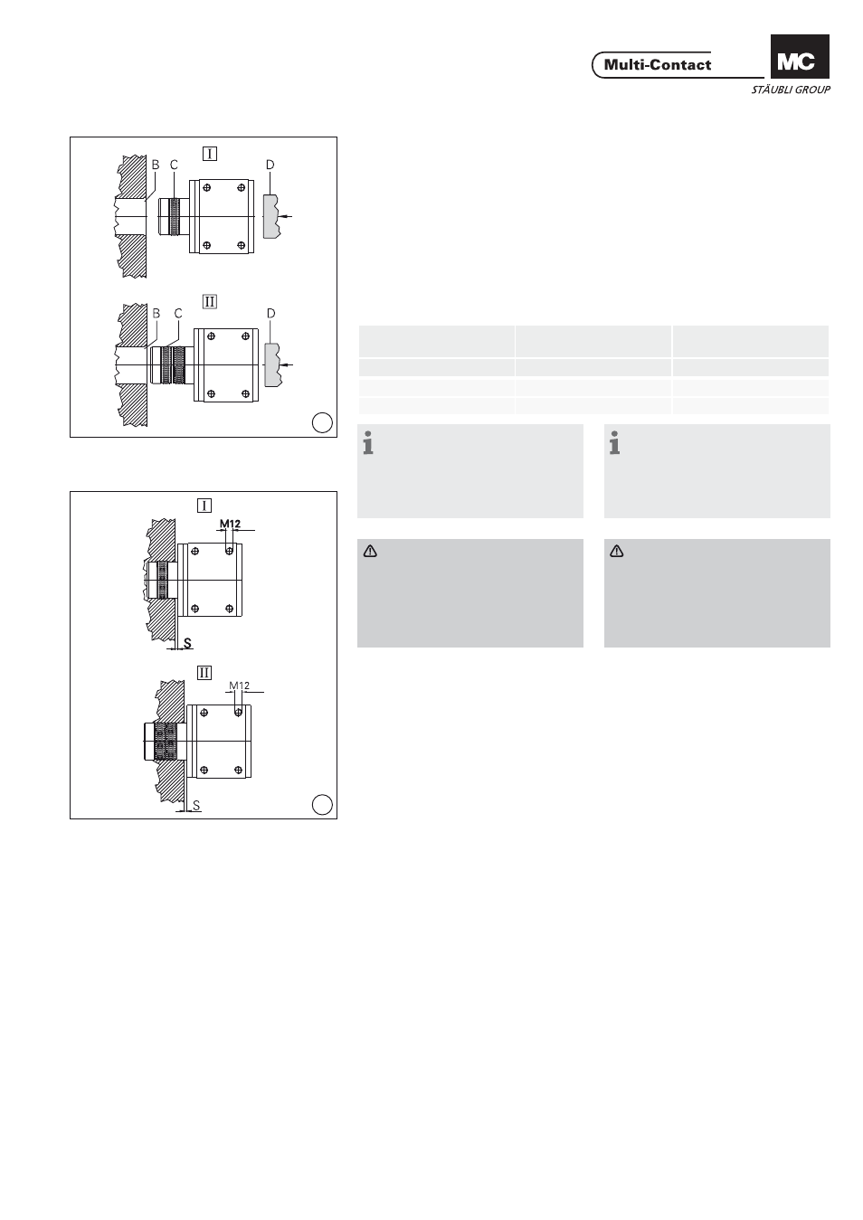
Montage von I und II
Assembly of I and II
(ill. 1+2)
Steckerteil I bzw. II des Drehkontaktes
in die vorgesehene Buchsenbohrung
B Ø 60mm-H7 bis zum Lamellenband
C von Hand einschieben. Dann mittels
Stempel D (min. Ø 70mm) bis auf
einen Spalt S (Tab. 1 + ill. 2)
einpressen.
(ill. 1+2)
Push the Ø 60mm plug I resp. II by
hand into the Ø 60mm-H7 socket hole
B upto the Multilam band C. Then
with the help of the press D
(min Ø 70mm) push in to the defi ned
gap S. (Tab. 1 + ill. 2)
Drehkontakt Typ
Rotary contact type
Einpresskraft
Push-in force
Spalt S
Gap S
N
mm
I. 15 kA
1000
2-4
II. 20 kA
2000
2-4
Hinweis:
Vor dem Einpressen Buchsenbo-
hrung B Ø 60mm-H7 mit Kontaktfett
Synthesin PDL250/01 (Bestell-Nr.:
73.1050) von Klüber Lubrication,
München leicht einfetten.
Note:
Before plugging, the Ø 60mm-H7
socket hole should be lightly greased
with contact grease Synthesin
PDL250/01(Order No.: 73.1050)
from Klüber Lubrication, Munich.
Achtung
Bei geschlitztem Wellen-Endteil
mit Klemmlasche (Buchse II),
muss vor der Montage die
Klemmlasche gelöst werden.
Nach dem Einpressen Klemmla-
sche wieder anziehen.
Attention
By the variant with slotted
„shaft“-end piece (socket II) and
clamping strap, the clamping
strap has to be removed before
mounting. After plugging, screw
the clamping strap back on.
Strom- und kühlmittelführende
Anschlussteile an die vorgesehenen
Anschlußstellen montieren. Anzugs-
drehmoment Schrauben
M12 --> 80Nm.
Connect the electrical and cooling
connections accordingly.
Tightening torque of the
M12 screws --> 80Nm.
Schmierdosen montieren und
Schmiermittelzufuhr freigeben. Der
Drehkontakt ist einsatzbereit.
Mount grease cup and open grease
fl ow. The rotary contact is ready for
use.