Multi-Contact MA220 Benutzerhandbuch
Multi-Contact Relais
Advanced Contact Technology
www.multi-contact.com
1 / 8
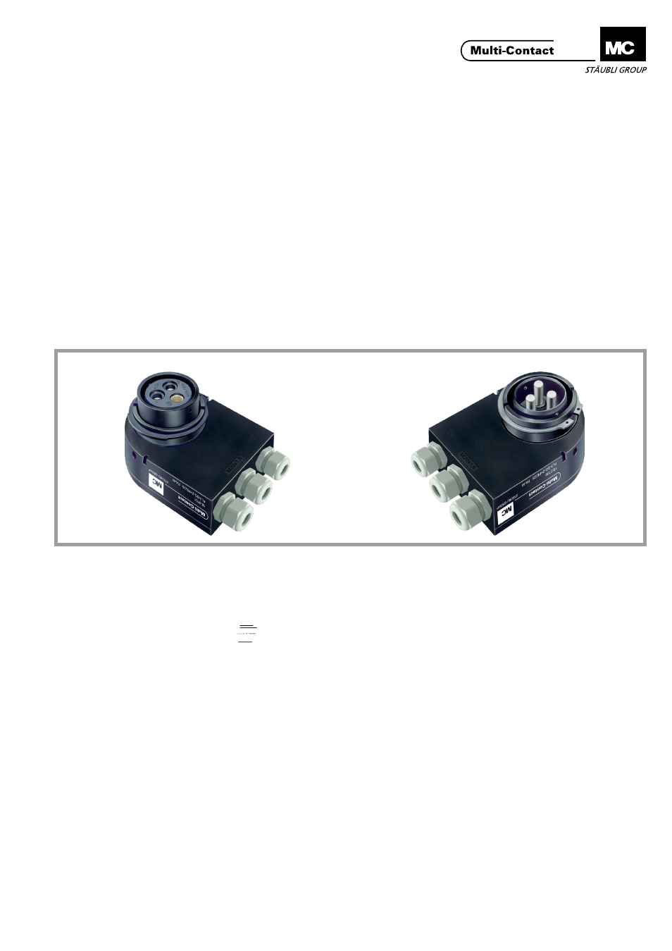
FL3-BG-2+PE/25PA
FL3-BG-2+PE/35PA
FL3-SG-2+PE/25PA
FL3-SG-2+PE/35PA
MA220 (de_en)
Montageanleitung
MA220 (de_en)
Assembly instructions
Stift- und Buchsengehäuse FL3-2+PE/...PA für
Werkzeugwechselsysteme
Pin and socket housing FL3-2+PE/...PA for tool-
changing systems
Inhalt
Sicherheitshinweise....................................................................2
Notwendiges Werkzeug ������������������������������������������������������������3
Vorbereiten der Leitung �������������������������������������������������������������3
Crimpen �������������������������������������������������������������������������������������4
Einbau der Kontaktstücke ����������������������������������������������������������4
Auswechseln der Kontaktgehäuse ��������������������������������������������5
Demontage ��������������������������������������������������������������������������������6
Beispiel Bohrplan �����������������������������������������������������������������������8
Content
Safety Instructions ......................................................................2
Tools required ............................................................................3
Cable preparation ����������������������������������������������������������������������3
Crimping ������������������������������������������������������������������������������������4
Fitting the contact pieces ����������������������������������������������������������4
Replacing the contact housing ��������������������������������������������������5
Disassembly ������������������������������������������������������������������������������6
Example drilling plan �����������������������������������������������������������������8
1. Stift-bzw� Buchsengehäuse Unterteil
2. Stiftgehäuse Vorderteil
3. Buchsengehäuse Vorderteil
4. Haltering
5. Gehäusedeckel
6. Federscheibe
7. Zylinderschrauben
8. Gewindestift (zur Sicherung von Teil 4 in Teil 1, rechts oder
links einschraubbar)
9. Kontaktstück gerade
10. Kontaktstück links
11. Kontaktstück rechts
1. Pin or socket housing bottom part
2. Pin housing front part
3. Socket housing front part
4. Securing ring
5. Cover
6. Lock washer
7. Screw
8. Setscrew (for locking part 4 in part 1, can be screwed in
on the left or right side)
9. Contact piece straight
10. Contact piece left
11. Contact piece right
Für Plattenabstand 12,5
+1/0
mm
Plattendicke 10
0/-0,1
mm
For plate spacing 12,5
+1/0
mm
Plate thickness 10
0/-0,1
mm
Kleine Nut / Small groove