Multi-Contact MA253 Benutzerhandbuch
Seite 5
Advanced Contact Technology
www.multi-contact.com
5 / 12
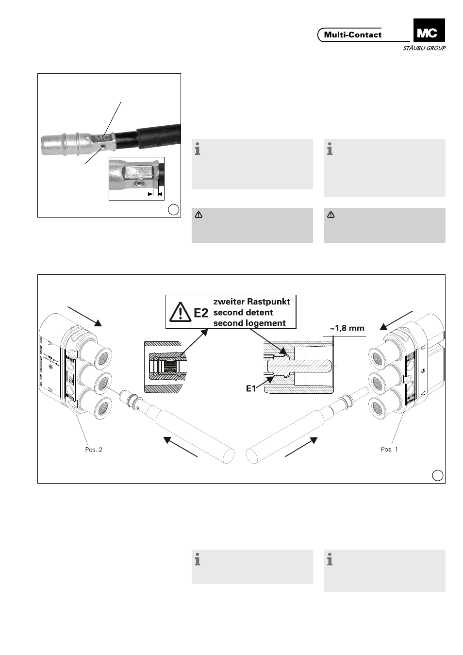
2 mm
12
13
Crimpen der Kontaktteile
Crimping-on the contact
parts
(ill. 12)
Leitung in die Crimphülse einführen
und während dem Crimpen festhalten
(ill. 12)
Insert cable into the crimping sleeve�
During the crimping operation keep
on pushing the cable into the sleeve�
Hinweis:
Litzen müssen vor und nach dem
Crimpen im Sichtloch sichtbar sein.
Wir empfehlen eine dreifache Crim-
pung mit einer 60° Drehung nach
der 1� bzw� 2� Crimpung�
Note:
Wire must be visible in the
inspection hole before and after
crimping� We recommend a triple
crimping operation with a rotation
of 60° after the 1st and the 2nd
crimping�
Vorsicht
Es dürfen weder vor noch nach
dem Crimpen Litzen aus der
Crimphülse hervorstehen�
Caution
No wire strands must protrude
from the crimping sleeve either
before or after crimping
Montage der Buchsenkontakte
Fitting the socket contacts
(ill. 13)
Leitung mit angecrimptem Kontakt
von hinten in die Isolation stossen bis
zum spürbaren Einrasten am zweiten
Rastpunkt (E2) (siehe Kontrollmass)�
(ill. 13)
By hand press cable with crimped-on
contact part into the insulation from
the back until it perceptibly engages
into place to the second detent (E2)
(see control dimension)�
Hinweis:
Die mittlere Kontaktkammer ist für
den PE-Kontakt und daher die Buch-
senseite “voreilend” ausgeführt.
Note:
The middle contact chamber is
intended for the PE, therefore mating
first and breaking last on the socket
side.
Crimpbereich
Crimping zone
Sichtloch
Inspection hole